Quote from: phatt on December 25, 2015, 01:12:21 AM
I have a hunch you might be over thinking this supply.
Wouldn't be the first time
 (or the fifth, or the tenth...) I tend to overengineer when I don't understand things as well. Then it gradually gets more sensible the longer I spend on it.
Quote from: phatt on December 25, 2015, 01:12:21 AM
I would just breadboard the first part (up to regulators) and read the output voltage.
Read Raw DCV with no load, see how fast the Voltage drops as you add a load.
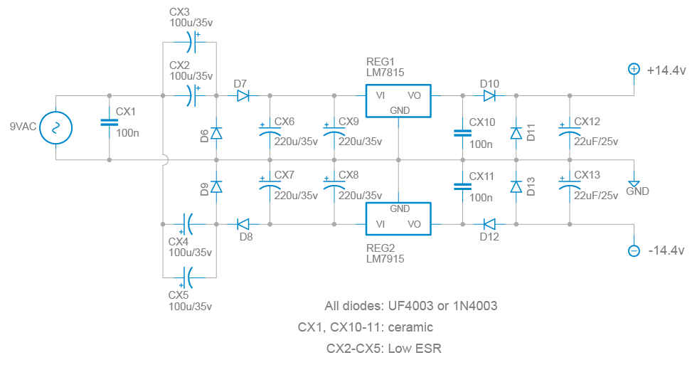
Will it regulate without a load? I saw a reference (here) to putting a 2.4k load resistor to ground after each regulator to get it to start regulating, so you could test out the supply before hooking it up to something live. Is this good practice? It would provide an extremely minimal load from what I understand, just enough to test, so it should have no real impact when the circuit is live.
Quote from: phatt on December 25, 2015, 01:12:21 AM
Regards the extra diode protection; AFAIK, If you read the fine print on data sheets for lower voltage regulation it is not needed and obviously pcb real estate is already a bit tight so you may wish to research that a bit more.
Yeah, the two sets of diodes after the regulator are actually both doing the same thing with regard to polarity protection, which I realized after thinking through it a bit more. I took out the ones that go to ground and left the ones in series so I could get the aforementioned voltage drop. I don't think I am at risk of having reverse-voltage damage to the regulators from the output caps discharging, but I suppose it doesn't hurt.
Thanks for your help. This has been incredibly valuable!