Menu

Show posts

This section allows you to view all posts made by this member. Note that you can only see posts made in areas you currently have access to.

Show posts Menu

Messages - kvandekrol

#1
Quote from: phatt on December 25, 2015, 01:12:21 AM
I have a hunch you might be over thinking this supply.

Wouldn't be the first time :) (or the fifth, or the tenth...) I tend to overengineer when I don't understand things as well. Then it gradually gets more sensible the longer I spend on it.

Quote from: phatt on December 25, 2015, 01:12:21 AM
I would just breadboard the first part (up to regulators) and read the output voltage.
Read Raw DCV with no load, see how fast the Voltage drops as you add a load.

Will it regulate without a load? I saw a reference (here) to putting a 2.4k load resistor to ground after each regulator to get it to start regulating, so you could test out the supply before hooking it up to something live. Is this good practice? It would provide an extremely minimal load from what I understand, just enough to test, so it should have no real impact when the circuit is live.

Quote from: phatt on December 25, 2015, 01:12:21 AM
Regards the extra diode protection; AFAIK, If you read the fine print on data sheets for lower voltage regulation it is not needed and obviously pcb real estate is already a bit tight so you may wish to research that a bit more.

Yeah, the two sets of diodes after the regulator are actually both doing the same thing with regard to polarity protection, which I realized after thinking through it a bit more. I took out the ones that go to ground and left the ones in series so I could get the aforementioned voltage drop. I don't think I am at risk of having reverse-voltage damage to the regulators from the output caps discharging, but I suppose it doesn't hurt.

Thanks for your help. This has been incredibly valuable!
#2
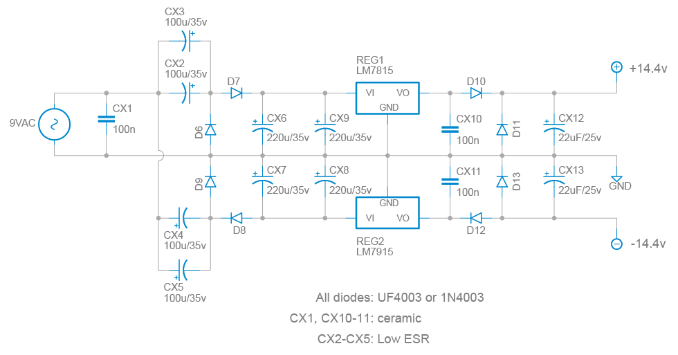
So, that Alesis doubler schematic led me down a three-day rabbit hole of studying these bipolar PSU schematics, reading through dozens of forum threads discussing it, and I ended up drawing this out as a candidate: (click to see the full thing)


Couple of notes.

1) The parallel caps primarily are for space concerns... the enclosure won't have enough height for bigger caps. For the 100uF booster caps, it also helps share the current load so they don't get too hot - but hopefully using low-ESR caps here will also help.

2) The series diodes after the regulator are for stability - I saw a few references to the 79XX and 79XX's latching up under certain conditions and this supposedly fixes that. I don't know for sure that they are necessary, but the original L5 actually runs on +/-14.4V, so the 0.6v diode drop gets it spot-on with the real thing.

3) The diodes to ground after the regulators are for protection - I saw them in a couple of similar PSU's and in some of the application notes for 78/79's so I am assuming they are good practice, or at the very least won't hurt anything.

Everything look good? This is my first time venturing this far from a 1:1 copy of an existing supply, and while I think I understand what everything does, I could really use a second set of experienced eyes.

We're only looking at a maximum of 200mA current needed... around 100 for all the ICs, and maybe 20mA per LED (there will be three of them). So I am hoping that this is plenty of filtering... I can't spare too much more space on the board!
#3
Quote from: phatt on December 21, 2015, 08:18:01 PM
If the MFOS supply takes up too much real estate then this will likely take up less space and deliver enough power. 10 VAC in will become  +/-25~28VDC at regulator inputs.

I'm not sure about the current ability of this idea (better minds may wish to verify) but it is often used in many of the Alesis micro series.
My Alesis Micro parametric EQ runs from a 1300mA 9VAC plug pak.
Phil.

I like that one a lot. I am guessing that for 15v, I'd need to go up to 12VAC wall wart and then use LDO regulators (LM2940 / 2990) since 12V * 1.414 is just a hair under 17V and the 7815/7915's need at least 2V of wiggle room.

Are the 220uF capacitors enough for a ~100mA current draw? Most of the schematics I've seen for these type of supplies call for 1000uFs' or 2200uF's, but it would be fantastic to be able to get away with this.
#4
Schematic:
http://www.rru.com/~meo/Guitar/Amps/Lab/Images/Lab_Series_L5_L7_L9_L11_scheme.jpeg

The supply itself would be pretty easy to implement, something like this:

http://www.musicfromouterspace.com/index.php?MAINTAB=SYNTHDIY&VPW=1910&VPH=813

...with a 15vAC adapter and regulators for +15 and -15. But the difficult part would be making space for it in the box, with either the 3300uF caps (MfOS project) or 1000uF like the V-Twin. Much more attractive to use an IC and a couple of caps if at all possible. Especially since at 12v bipolar it should only draw an absolute max of 70mA...
#5
I am knee deep in a project to put the Lab Series L5 preamp in a 1790NS enclosure (EHX "XO" series, or around the size of a Fulldrive)

It'll be pretty well identical to the original, except it'll be channel-switchable, with the initial gain stage shared between both channels and a footswitch to switch it from there. I am also replacing the CA3094 with a CA3080 + discrete Darlington per the original schematic in the 3904 datasheet.

Anyway: I have a couple of questions regarding power handling and biasing.

First: the supply. I don't think there is any good reason to stick with the +/-15V from the original, when compared with the difficulty of making such a supply (not to mention the danger of "rolling your own" from AC power). I am planning on using a LT1054 voltage inverter that should work with either 9V or 12V.

The LT1054 can handle up to 100mA. So, I crunched the numbers on the L5 and came up with the following power requirements:

CA3080: 1.2mA each (x2) = 2.5mA
LM741: 3mA each max (datasheet says 1.7-2.8mA) (x2) = 6mA
JRC4558D: 6mA each (3.5 - 5.7 datasheet) x12 = 72mA
LF356N: 10mA each (5-10 datasheet) x1 = 10mA (max)

Total: 90.5mA if everything was at the very top of its specified range. This is also based on their power requirements assuming +/-15v. The draw should be around 20% less at +/-12V and 40% less at +/-9V, so the full circuit should be significantly less than the LT1054's capacity.

So my first question is: Should this theoretically work OK? Or have I made a mistake in my calculations someplace?

Second question is much easier. The trimming/biasing/tuning methods for the L5 are well documented in their service manuals, and the schematic itself is loaded with test voltages at major junctions and test points. If I am using a supply lower than the standard +/-15V, should I aim for the voltages and test results they specify (since we are nowhere near the rails no matter if it's running at +/-9v, 12v or 15v) - or should I plan on everything being proportionally smaller?
#6
I'm building the preamp by itself in a rackmount enclosure (with the power supply you drew up for me a few months ago on the preamp forum!). So I won't be tackling the power amp section at all, but it's complex enough even without it!

Other than removing the reverb, it will be a part-for-part clone. I'll probably post it up here as a project once I'm finished, along with a project file for the PCB, in case anyone is interested. It may be a year from now - we'll see!
#7
http://www.netads.com/~meo/Guitar/Amps/Lab/Images/Lab_Series_L5_L7_L9_L11_scheme.jpeg

I'm in the process of designing & building a Lab Series L5 preamp clone to put in a rackmount enclosure. I think I have everything else figured out but this: I want to remove the reverb from the circuit entirely. I think I know how to do it, but I'm looking for some independent verification that I'm not missing anything!

If I was to eliminate the wire labeled "4" that goes from the preamp board to the power supply board, and eliminate R165 (18k) that goes between the multifilter and the reverb pot, and then remove the whole section between wires 5 & 6 and R165, would that do it? Do any of those components serve a purpose other than reverb, such that I would lose out on anything if they weren't there? Is the multifilter control affected at all by this?

Everything else related to the reverb appeared to be on the power supply board itself, which I won't be using...
#8
I wondering if I'm making this too complicated... I noticed that Jack Orman has a pedalboard power supply project here where he gets multiple +9v, a +12v, and a -9V from a single 18v DC supply.

Would it be possible, using a charge pump like a MAX1044 along with regulators, to get +/- 15V from an 18v wall wart?
#9
In series with the primary - meaning, the fuse should go between the main power cable and the transformer? (or more accurately, between the power switch and the transformer)
#10
Next question, and probably the last until I actually build the thing, but what about a fuse? Is there any need for one, or for any other type of protection against failure or worst-case scenarios?
#11
Great! Thank you. Are there any concerns about the power supply being unregulated? And is there a functional difference between the W02 and W04G bridge rectifiers?
#12
JM, could you draw up a diagram or point me in the direction of something that would help me visualize that? Sounds like it would be loads cheaper and more simple to do it that way - but it's definitely something I want to get right the first time, rather than experimenting and trying to figure it out myself, given the risk involved in the case of failure :)

Is there a better transformer I could use, like one that mounts to the chassis? I'm not crazy about the PCB mount but was unable to find anything similarly sized that was chassis mounted. Now that I have a better idea of what to search for, I found these:

http://www.mouser.com/ProductDetail/Hammond-Manufacturing/187B24/?qs=sGAEpiMZZMv4oUrzpPKU3J%252b8YG9gjyY6t272u8IOEn0%3d

http://www.mouser.com/ProductDetail/Hammond-Manufacturing/187C24/?qs=sGAEpiMZZMv4oUrzpPKU3Eihc0fH5wJ2%252beffhomZ0Ik%3d

First is 6VA, second is 12VA, and I believe both will fit in a 1U (the 12VA is 1.61in tall, not sure how much clearance is needed in the inside of the enclosure). I prefer the quick connects, as well.
#13
Preamps and Effects / Transformer for 15v bipolar supply
December 28, 2010, 07:26:34 AM
I'm building a preamp that needs a 15v bipolar supply. The catch is that I have never built anything that required a transformer; all of my electronic adventures have been solidly 9 volts with a wall-wart. So I'm looking for some advice!

The preamp will be in a 1U rack case, so the height of the transformer is important.

I will probably be using this as the project for the power supply:
http://www.paia.com/proddetail.asp?prod=K83&cat=50

I did some poking around and found this transformer, which looks like it'll do what I need, for a very reasonable price:

http://www.mouser.com/ProductDetail/Hammond-Manufacturing/164G20/?qs=sGAEpiMZZMtz8P%2feuiupSThvwaRcnmu81WhoAji7k8o%3d

I also found the ST-5-20 on this page, which is very similar in specs:

http://www.signaltransformer.com/content/white-goods-splittran-low-power-transformer

Is one of these what I need, or is there something better I should use? I don't think the preamp will pull more than about 200 mA based on the components, but I went with a 600mA supply just to be safe. They are both PCB-mount, but I figured I could just use a piece of perfboard for that.
#14
I checked on the NTE cross reference (NTE172A). Everything looks nearly identical (except the "maximum" ratings are of course much higher on the NTE), but I'm wondering about the gain. The D16P1 has a range of 2k-70k, while the NTE's is 7k-70k. In this application, would that make any difference?
#15
Thanks for the responses! Here's more info: this would be a direct replacement for the D16P1 in the Lab Series L5 compressor circuit (Q103, here.) Having gone from a complete soldering novice a year ago to now being somewhat competent with analog circuits, primarily due to the long process of repairing an L5 (which is documented in nearly all of my previous posts on this forum :)), I am toying with the idea of building an L5 preamp from scratch - for the challenge of it, and because I want to make it rackmountable. The D16P1 is the only part that isn't still available.