- Welcome to Solid State Guitar Amp Forum | DIY Guitar Amplifiers.
Solid State Guitar Amp Forum


 Recent Posts
-
yamaha g100 1x12 version 3, amp issue - no sound (sometimes)
by saturated
[Today at 01:23:39 PM] -
More low hanging fruit
by saturated
[October 11, 2026, 09:35:46 PM] -
LND150 Buffer for a Belton BTDR-3 as input of a Small Stereo Guitar Amp
by Kagliostro
[October 11, 2026, 10:56:39 AM] -
Fender sidekick 25R
by Jazz P Bass
[October 10, 2026, 09:12:12 AM] -
There's nothing to be gained from this
by g1
[October 08, 2026, 11:37:56 AM]
Recent posts
#1
The Newcomer's Forum / Re: yamaha g100 1x12 version 3...
Last post by saturated - Today at 01:23:39 PMI would look at IC 112 and IC 113 (upc7915a and upc7815a) but I don't see any voltages there on the schematic 
#2
The Newcomer's Forum / Re: yamaha g100 1x12 version 3...
Last post by mentalmidget - Today at 08:14:38 AMso again. the other day, the amp went silent for a couple minutes, then started working again. i checked the resistor, it was properly seated, wasn't loose. im starting to think it might be a relay issue?
#3
The Newcomer's Forum / More low hanging fruit
Last post by saturated - October 11, 2026, 09:35:46 PMThis looks pretty simple but I wanted to try it
You cannot view this attachment.
I did not find a 7505 but I did have a 7808ct so I hooked it up and went with it
Looks like I forgot about having the capacitor close
You cannot view this attachment.
And the predictable results (I hope )
You cannot view this attachment.
It still was an eye opener seeing DC voltage appear at the output before the minimum input level
I wondered if the results might be wacked without a load resistor
Also at the end I felt the metal tab with my hand but it wasn't hot
Next I have to add some resistors and do some more stuff
Hmm now I hope these results agree with the data sheet
You cannot view this attachment.
I did not find a 7505 but I did have a 7808ct so I hooked it up and went with it
Looks like I forgot about having the capacitor close
You cannot view this attachment.
And the predictable results (I hope
)You cannot view this attachment.
It still was an eye opener seeing DC voltage appear at the output before the minimum input level
I wondered if the results might be wacked without a load resistor
Also at the end I felt the metal tab with my hand but it wasn't hot
Next I have to add some resistors and do some more stuff
Hmm now I hope these results agree with the data sheet
#4
Tubes and Hybrids / Re: LND150 Buffer for a Belton...
Last post by Kagliostro - October 11, 2026, 10:56:39 AMThanks Mick
I'll go there and see if I find something interesting
----
To draw my LND150 pre/buffer I've read a lot on many webpages and I would like to know how consider it a Solid State circuit expert, to me it is the first afford to put together something that isn't a vacuum tube
Franco
I'll go there and see if I find something interesting
----
To draw my LND150 pre/buffer I've read a lot on many webpages and I would like to know how consider it a Solid State circuit expert, to me it is the first afford to put together something that isn't a vacuum tube
Franco
#5
Tubes and Hybrids / Re: LND150 Buffer for a Belton...
Last post by Tassieviking - October 11, 2026, 09:20:15 AMIf you are a tube fanatic then perhaps you would find the tube reverb pedal that Conspiracy To Commit Electronics has designed, he sells PCB's only for his designs but Musikding in Europe sells kits I believe that Musikding puts together with his PCB's. If nothing else you can check out the circuit and also check out the forum on Talkbass or PedalPCB. The best forum is the PedalPCB one as people talk about the builds and any problems people run into and also any mods they have done. He has stopped posting on TalkBass because he answered questions people asked that went against TalkBass rules and he constantly got suspended, he was not aloud to answer questions about what he thought about the sound of his pedals or any upcoming completed pedals that he made under his SushiBox FX brand even though people would constantly ask him.
They are all made for stompboxes but you could incorporate them into an amplifier if you wanted to.
https://c2celectronics.com/
https://forum.pedalpcb.com/forums/sushiboxfx/
https://www.talkbass.com/threads/conspiracy-to-commit-electronics-megathread.1640493/page-37
Cheers
Mick
They are all made for stompboxes but you could incorporate them into an amplifier if you wanted to.
https://c2celectronics.com/
https://forum.pedalpcb.com/forums/sushiboxfx/
https://www.talkbass.com/threads/conspiracy-to-commit-electronics-megathread.1640493/page-37
Cheers
Mick
#6
Tubes and Hybrids / Re: LND150 Buffer for a Belton...
Last post by Kagliostro - October 10, 2026, 12:07:27 PMThanks tonyharker
OK I repurpose the post without the use of IMGUR
Hi, my name is Franco
I'm a class of 1953 tube enthusiast, known as Kagliostro at DIYItalia, EL34World, AmpGarage, and aggh.net
I have a Telefunken Musikus 5062 Stereo Suitcase Turntable (2 x 4W) that I want to convert into a small guitar amp (EDIT: 2 x Fender AA764 circuits)
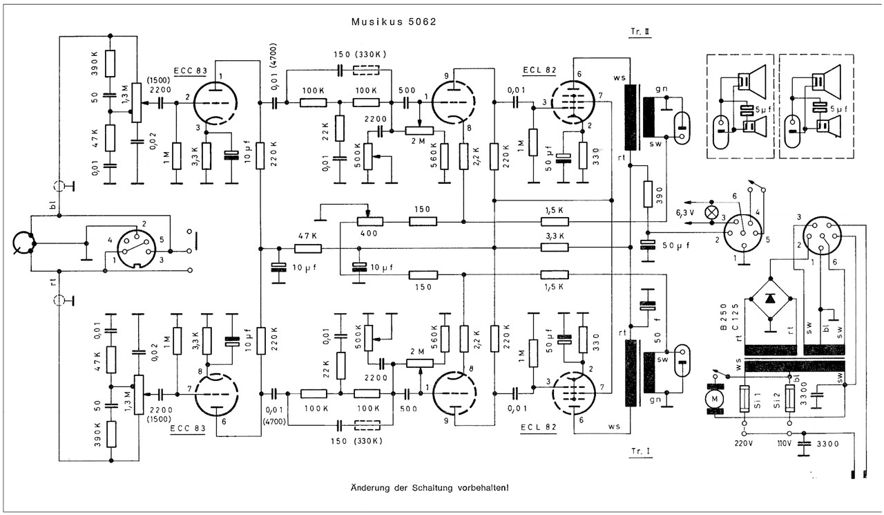
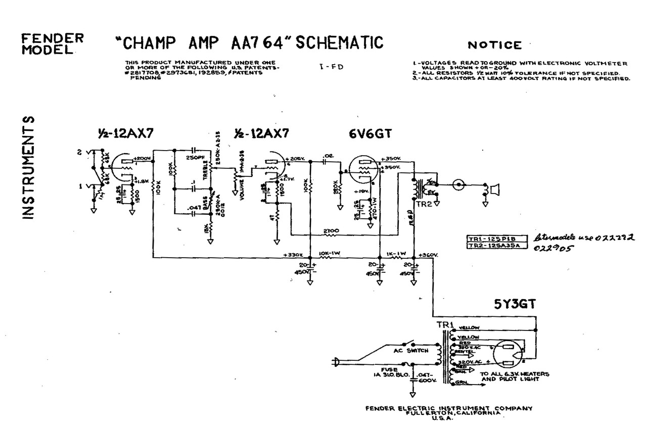
As it's a stereo build, I'm thinking of using a V-front cabinet inspired by the Gibson GA-79RVT to help widen the stereo field
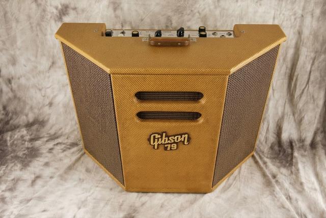
To further expand the sense of space, I decided to use a Belton BTDR-3 reverb module (Mono IN - Stereo OUT)
http://accubell.eparthosting.co.kr/upload/product/file0_1650341049.pdf
However, at the input I had to insert a buffer stage to ensure proper impedance matching and to attenuate the signal level so as not to overdrive the Belton module (BTDR-3 Spec. Z IN = 10K - Max 1.5V - Z OUT = 220R - OUT -3 db)
While I understand something in tube circuit, solid-state designs are definitely not my suit!
With some effort and external help, I put together this LND150 buffer stage
Z IN = ~700K - Z OUT = ~650R - Gain on Q1 = 8.9x - Gain at the OUT = 1.87x
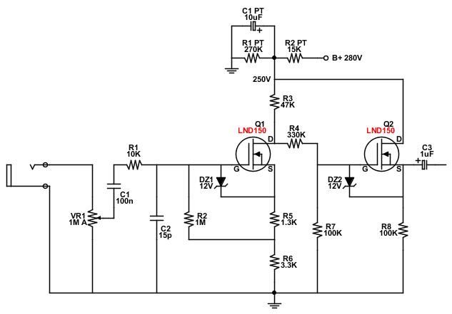
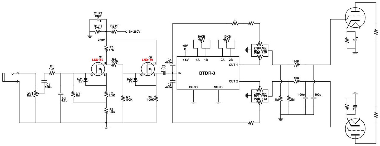
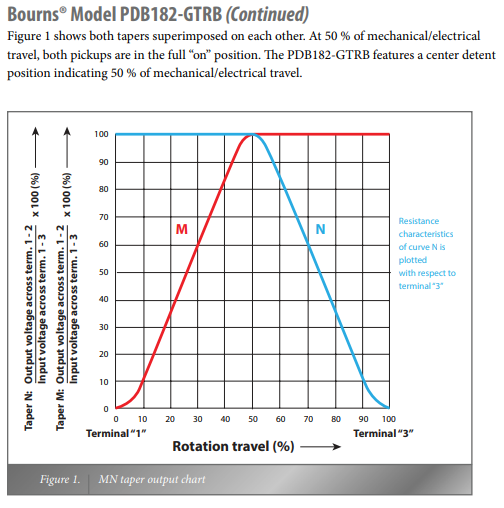
Please let me know if you notice any flaws or incorrect component values in my approach, or if it all seems completely wrong to you!
Many Thanks
Franco
OK I repurpose the post without the use of IMGUR
Hi, my name is Franco
I'm a class of 1953 tube enthusiast, known as Kagliostro at DIYItalia, EL34World, AmpGarage, and aggh.net
I have a Telefunken Musikus 5062 Stereo Suitcase Turntable (2 x 4W) that I want to convert into a small guitar amp (EDIT: 2 x Fender AA764 circuits)
As it's a stereo build, I'm thinking of using a V-front cabinet inspired by the Gibson GA-79RVT to help widen the stereo field
To further expand the sense of space, I decided to use a Belton BTDR-3 reverb module (Mono IN - Stereo OUT)
http://accubell.eparthosting.co.kr/upload/product/file0_1650341049.pdf
However, at the input I had to insert a buffer stage to ensure proper impedance matching and to attenuate the signal level so as not to overdrive the Belton module (BTDR-3 Spec. Z IN = 10K - Max 1.5V - Z OUT = 220R - OUT -3 db)
While I understand something in tube circuit, solid-state designs are definitely not my suit!
With some effort and external help, I put together this LND150 buffer stage
Z IN = ~700K - Z OUT = ~650R - Gain on Q1 = 8.9x - Gain at the OUT = 1.87x
Please let me know if you notice any flaws or incorrect component values in my approach, or if it all seems completely wrong to you!
Many Thanks
Franco
#7
Tubes and Hybrids / Re: LND150 Buffer for a Belton...
Last post by tonyharker - October 10, 2026, 10:15:49 AMPlease dont use imgur to host your pictures. No one in UK can see them as there is a block on it. We are not allowed to see anything on the imgur site.
#8
Schematics and Layouts / Re: Fender sidekick 25R
Last post by Jazz P Bass - October 10, 2026, 09:12:12 AMHuh.
It came right up on Google AI.
It came right up on Google AI.
#9
Schematics and Layouts / Fender sidekick 25R
Last post by Stitch45 - October 10, 2026, 06:09:41 AMI am in need of a schematic for a Fender 2 input sidekick 25 reverb as I have acquired one that someone totally screwed up the input wiring and I cant find one via google.
Thanks for any help.
Thanks for any help.
#10
Tubes and Hybrids / LND150 Buffer for a Belton BTD...
Last post by Kagliostro - October 09, 2026, 11:29:29 AMHi, my name is Franco
I'm a class of 1953 tube enthusiast, known as Kagliostro at DIYItalia, EL34World, AmpGarage, and aggh.net
I have a Telefunken Musikus 5062 Stereo Suitcase Turntable (2 x 4W) that I want to convert into a small guitar amp (EDIT: 2 x Fender aa764 circuits)


As it's a stereo build, I'm thinking of using a V-front cabinet inspired by the Gibson GA-79RVT to help widen the stereo field

To further expand the sense of space, I decided to use a Belton BTDR-3 reverb module (Mono IN - Stereo OUT)
https://www.amplifiedparts.com/sites/default/files/associated_files/btdr-3.pdf
However, at the input I had to insert a buffer stage to ensure proper impedance matching and to attenuate the signal level so as not to overdrive the Belton module ( BTDR-3 Spec. Z IN = 10K - Max 1.5V - Z OUT = 220R - OUT -3 db)
While I understand something in tube circuit, solid-state designs are definitely not my suit!
With some effort and external help, I put together this LND150 buffer stage
Z IN = ~700K - Z OUT = ~650R - Gain on Q1 = 8.9x - Gain at the OUT = 1.87x


Please let me know if you notice any flaws or incorrect component values in my approach, or if it all seems completely wrong to you!
Many Thanks
Franco
I'm a class of 1953 tube enthusiast, known as Kagliostro at DIYItalia, EL34World, AmpGarage, and aggh.net
I have a Telefunken Musikus 5062 Stereo Suitcase Turntable (2 x 4W) that I want to convert into a small guitar amp (EDIT: 2 x Fender aa764 circuits)
As it's a stereo build, I'm thinking of using a V-front cabinet inspired by the Gibson GA-79RVT to help widen the stereo field
To further expand the sense of space, I decided to use a Belton BTDR-3 reverb module (Mono IN - Stereo OUT)
https://www.amplifiedparts.com/sites/default/files/associated_files/btdr-3.pdf
However, at the input I had to insert a buffer stage to ensure proper impedance matching and to attenuate the signal level so as not to overdrive the Belton module ( BTDR-3 Spec. Z IN = 10K - Max 1.5V - Z OUT = 220R - OUT -3 db)
While I understand something in tube circuit, solid-state designs are definitely not my suit!
With some effort and external help, I put together this LND150 buffer stage
Z IN = ~700K - Z OUT = ~650R - Gain on Q1 = 8.9x - Gain at the OUT = 1.87x
Please let me know if you notice any flaws or incorrect component values in my approach, or if it all seems completely wrong to you!
Many Thanks
Franco