Menu

Show posts

This section allows you to view all posts made by this member. Note that you can only see posts made in areas you currently have access to.

Show posts Menu

Messages - sewage666

#1
I'm sure the parts are from overseas... Does any US company make transistors anymore? I just think slapping some knobs on a pedal and calling it "made in the USA" is a stretch. Better than not, though, I guess.

Thanks for the link to the videos! I'll check it out.
#2
Is it really? Not to be a naysayer, but EHX makes that same claim. Truth be told, a lot if not all their circuit boards are populated overseas, with just the final box assembly occuring stateside. I imagine that's common practice.
#3
Amplifier Discussion / Re: Fried Ampeg SVT-200T
July 17, 2012, 10:01:38 PM
Speaking of n00b... I hate to admit this, but in the interest of total transparency for any future readers this could help, I shall.

I had test points 6 and 7 in marked wrong. Oi vey. I was thinking about it on the way home from work, traced the circuit again, and found I'd been testing in the wrong place. I adjusted the variable resistor, and they're well within their test range now.
#4
Amplifier Discussion / Re: Fried Ampeg SVT-200T
July 17, 2012, 07:44:17 PM
@Enzo, of course this is true... I guess what I hate is that I'm one of those n00bs who has a hard time not taking the analogy too seriously, thinking of electricity "flowing."

I definitely could use an "Electronics 101" course, but since I'm fixing all my own stuff because of a lack of cash flowing, it'll be some time.
#5
Amplifier Discussion / Re: Fried Ampeg SVT-200T
July 17, 2012, 01:32:29 PM
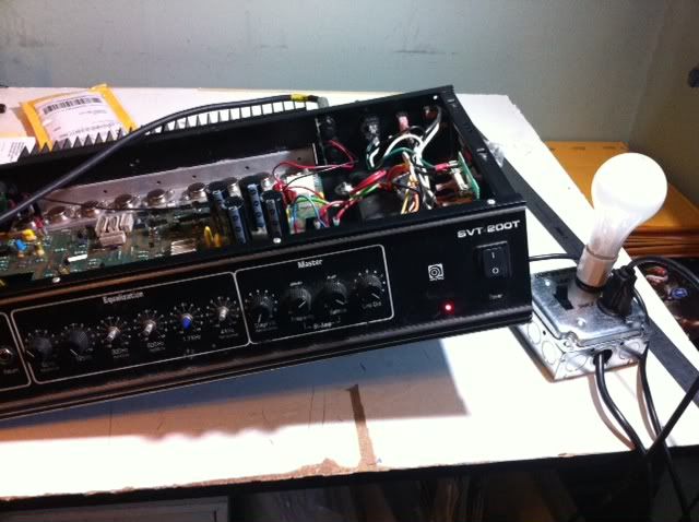
Update:

I built a limiting lamp. Replaced the four 1n914A diodes D10-13...


In my impatience, after testing Q11-18 multiple times now, I just decided to fire it up. The light bulb went bright, then dim as it should.

I checked the test points... 6 and 7 are reading 57 and -57 DC. What the F? TP 3 is still in negative mV. On the happy side, 4 and 5 are right where they're supposed to be.

Out of curiosity, I plug into a speaker and guitar cord anyway, and pow... buzz. Loud buzz. Plug in a guitar, and FINALLY this amp is breathing again. It's loud. It's the first time I've heard this thing make a peep in years and years, and it sounds awesome.

Okay, I probably broke a lot of rules here. I have a degree in painting, so, I'm an idiot. Also, I meant the diodes were OPEN, not shorted... another failure of my lexicon in electronics. This project, however, has schooled me immensely.

I'm gonna do some more testing, because really, I'm trying to figure out what I did wrong on the test points. In the meantime, my testing will be more fun, because this amp works again! Thanks for all the help!

P.S. I kinda hate the water analogy for current. I get it, I've thought about it. I think just about every analogy fails eventually, though, some quicker than others. It's like saying the Internet is a series of tubes. It's actually a decent metaphor, if you think about data flow, but it just doesn't translate.
#6
Amplifier Discussion / Re: Fried Ampeg SVT-200T
July 12, 2012, 10:38:08 AM
Quote from: Roly on July 12, 2012, 06:47:45 AM
I'm confused by your "D10 and D13 were passing no voltage".  Components pass current and have voltage across them, or between points.

Specifically did you find D10 and D13 open or shorted?

Sorry, nomenclature fail... There is no voltage across them either direction, so they're passing no current. They're shorted.

Quote from: Roly on July 12, 2012, 06:47:45 AM
Patience is something you must have if you are going to solve these sorts of problems - they simply don't yield to macho gust and bust but to thorough and methodical.

Do I get points for being pissed at every diode, but methodically testing them all in order? :)
#7
Amplifier Discussion / Re: Impedence question....
July 11, 2012, 04:31:02 PM
If you wanna spend $1, use a dollar bill. It's a strong fabric-woven paper.

I've had success on the road saving a speaker with a hole in the cone by patching on both sides with toilet paper and coating it in nail polish. I didn't wanna spend the $1 on my guitarist's speaker. It wasn't like new, but it sounded a ton better.
#8
Amplifier Discussion / Re: Fried Ampeg SVT-200T
July 11, 2012, 01:22:19 PM
I hadn't seen your response until I'd gone mad and decided I needed to test every diode!!! Well, I tested them in place, and any that didn't read normal I tested out of circuit as well. Of course, that was just about every diode. Fruitless search?

Not necessarily... I found D10 and D13 were passing no voltage... these are connected to the bases of Q7 and Q8. Also suspiciously near the original resistor burn out zone. D12 also tested funny (was reading as passing 2x as much voltage as other 1N914s) so I'm just going to replace that whole array of diodes there.

My parts are already on there way via snail mail... When I get them put it in, we'll again 1. see what happens and then 2. I'll start tests down the rails as you've suggested.

Thanks a lot for your help and patience, Roly!
#9
Amplifier Discussion / Re: Fried Ampeg SVT-200T
July 10, 2012, 12:23:41 PM
Oh boy, that's my bad!! Those voltages aren't on either side of r30, those are TP6 and TP7. I realize now I wrote them at a different spot before... Sorry! I wiped clear my old readings and just re-added each point.
#10
Amplifier Discussion / Re: Fried Ampeg SVT-200T
July 10, 2012, 02:30:35 AM
And, I'm back.

I got my parts in the mail... I replaced both diodes on the 16V rail, D20 and D21. Both, just because I thought I should. I got my +16V back, I assume the diode was bleeding to ground.

I plugged in my two new NE5532 ICs... and nothing. Well, not nothing. I ran the sine wave back into the power amp line-in, and it definitely was coming through. It's coming through about the level before I replaced the shorted jack. Very quiet. I tried the same trick to short the jack connection, in case that was the problem, but no effect. I also tried to short the speaker jack, no result. Messed with the biasing resistor (and put it back to where it was), no result.

I measured across the .33Ohm 5W resistors and didn't get a reading. They're stone cold, too.

I re-measured all my test points, and there is definitely still some discrepancies from the table. Namely 3 (giving me a negative DC voltage reading) and 14 (way off from the table)

Again, I'm stumped. I'm gonna approach this again with daytime eyes, but maybe someone else has a thought? Thanks. New schematic and test point results attached!
#11
Amplifier Discussion / Re: Fried Ampeg SVT-200T
July 06, 2012, 11:44:57 AM
QuoteD20:  presuming you didn't get your fingers into the act, and you measured it with one end disconnected, this is very wrong - should measure about 600mV one way and open circuit the other.  You can't get a reliable reading in circuit (because of C10).  But these measurements won't give you 6 volts on the supply either.

I'm inclined to think there is actually nothing wrong with D20 or R24.

I did all the measurements out of circuit. R24 is fine. D20 tested funny, so I compared it D21, which tested good. I've got a batch of 1N4745As on their way to me now.

QuoteNow previously you had about the correct voltages on TP4 and TP5, and more importantly TP10 and TP11.  If the +16V is now only +6V then something on the +16V rail is drawing too much current, and the most likely suspect is one of the op-amps powered off that rail.

Pull the one you have socketed (IC1?) and see if that restores the 16V supplies.  IC1 is not needed in place to measure the DC conditions of the output stage.

Luckily I socketed both ICs, because I had the same thought... but unluckily, it didn't make a difference. I traded around ICs in both. My TL072s were recycled from some random circuit boards I found in a salvage store, so their reliability is suspect. I've ordered NE5532s.

When I get these parts replaced that I know are variables, I'll be taking new test point notes. Or, maybe I'll be playing loud bass through my now working amp. I'd prefer the latter!
#12
Amplifier Discussion / Re: Fried Ampeg SVT-200T
July 06, 2012, 01:40:19 AM
Also just noticed... Q6 (bias transistor) is listed as 2N3402 on schematic, but the actual part in my amp is a 2N3403. Could be equivalent?
#13
Amplifier Discussion / Re: Fried Ampeg SVT-200T
July 06, 2012, 01:23:28 AM
Ha! I SWEAR I checked the continuity of that switch jack... in fact, checking it again out of circuit, the old jacks test fine. They just didn't work... can the metal corrode or something where it starts to act like a resistor? All I know is this is the second time I had this same mysterious problem with old Cliff jacks... test fine, but don't work in circuit.

Moving on...

Fired up the amp again today to update my test points, and +16v rail went down to around 6? +61 rail is okay (tested around +71)... but right after the 1.5kohm resistor (which tests okay), voltage drops with 66 volts measuring across resistor. If the resistor isn't bad, then where is that voltage going?
Measured D20: measured 1.7 one way, .3 the other. Bad diode?! Could I have shorted that out?

Tested
Q6: good
Q7: good
Q8: good
Q2: good
Q3: good

Moving on and waiting for some parts in the mail...
#14
Amplifier Discussion / Re: Fried Ampeg SVT-200T
July 04, 2012, 09:16:51 PM
Big update... I was trying JM's test, and I started getting the faintest hint of a sound coming through my speaker. A little 500Hz sinewave I was playing through my iPod into the line in. Weird, I thought. I switched ICs into the sockets I'd installed, and it didn't make a difference. So I think the ICs were fine.

While I was probing to do the voltage test, I accidentally made contact on the tip end of the line-in jack/switch. Noise. Big noise. I switched my iPod onto The Fog soundtrack (yay) and there it was, nice and loud, coming through the power amp section. Then I accidentally bumped my probe into the thermal switch. POP! I blew one of the NE5532s. So I swapped a TL072 in.

I'd had this same kinda problem with the effects loop of a VH-140C (it was cutting the signal in and out), so I had some of the weird L leg Cliff jacks that Ampeg used in the 90s lying around. This is all despite the original jack continuity testing fine, keep in mind... same thing on the VH-140C. I can't explain it.

So, I swapped the jacks for new ones, and behold! My problem was mechanical all along (and I feel really dumb)! Many thanks in helping me trudge along, or I wouldn't have kept testing. And I hate Cliff jacks, now. BUT...

Now that the amp is amplifying, it's buzzing and distorting REALLY bad, and the signal cuts abruptly while the instrument's strings are still decaying. It also only makes noise if the volume and gain are at least half way up. Could this be because of the TL072? I guess I can't really answer that until I order some new NE5532s and get this thing back to spec. Could it be the octocoupler? Could be from the original damage inflicted the first time it fried, or damage I just did shorting the thermal switch? Time to stop for now, order some ICs, and then watch fireworks. Happy fourth!
#15
Amplifier Discussion / Re: Fried Ampeg SVT-200T
July 04, 2012, 03:23:56 PM
Quote from: J M Fahey on July 04, 2012, 02:06:18 PM
Agree and add: please do not use an NTE equivalent if at all possible.
NE5532 are very common, order a couple from a known supplier , keep tem as spares.
That said, they are not even needed in IC1, *very* light duty there, you can use a common TL072

I replaced IC1 with a TL072. No result.

Quote from: Roly on July 04, 2012, 11:06:10 AM
I mean measure the voltage across each of R31 to R38, probe at each end of each resistor in turn to measure the voltage between the ends of each resistor.  R31 and 32 should have about a volt across each, while the rest should have about 10 to 20mV across each.  Basically this is to check that the two drivers, Q11 and 12 are passing about the right current through R31 and 32, and that each of the output transistors Q13 to Q18 are all passing about the expected current, and therefore can be presumed healthy.

I've measured 0V passing through R31 or R32. That can't be good. Same for the R33-R38. I assume since these are ceramic resistors, they should also be running at least a little hot, which they aren't. I just pulled out Q7, Q9, Q11 and tested them according to first test here:
http://www.kpsec.freeuk.com/components/tran.htm#testing
I don't know if there's a better, more assured way to see if a transistor is failing?

I'm baffled what to try next. I'm beginning to understand why, years ago, one tech I asked about working on this amp said it was on a short list of amps he refuses. Oi vey.