Menu

Show posts

This section allows you to view all posts made by this member. Note that you can only see posts made in areas you currently have access to.

Show posts Menu

Messages - galaxiex

#436
Amplifier Discussion / Re: DIY amp directions
September 13, 2014, 12:15:05 AM
Pic LR 007

I have a PF5102 JFET that has the same pin out as the MPF 102.
From the left with the flat side facing you and the leads pointing down. 1. Drain 2. Source 3. Gate
You see on the data sheet it says "N-CHANNEL SWITCH"
No big deal, this JFET can still function as a preamp, it doesn't have to be used as a switch.
The designers may have intended for it to be a switch, and optimised it for such, but it will work just fine as a preamp in this circuit.
I always like to get the data sheet for whatever device I'm working with, for the proper pinout.
It's important to get it installed correctly!

Pics LR 008 to 010
Different views of how/where the JFET is placed.
#437
Amplifier Discussion / Re: DIY amp directions
September 12, 2014, 11:53:26 PM
Ok following Roly's latest drawing of Lauren's Ruby here is how I started.

Note nothing is soldered yet.

Pic LR 001

I've got the board, and the picture printed.
Marked the board with the + and - to help remember which is which.  ;)
Notice there is also a "1" mark at the top to help me remember where Pin 1 is in relation to the socket.
If you don't have a socket you could just place the IC on the board.

Pic LR 002 to 006

Here I have placed all the capacitors to see how it looks.
Looks good!  :)

Notice in pic LR 006 you can see the - minus sign on the 2 electrolytic caps.

On to the next...
#438
Amplifier Discussion / Re: DIY amp directions
September 12, 2014, 11:39:42 PM
Show off...  ;)  :)

(... but I notice they are not cascaded to have 4 gain stages in one amp,
but rather, 4 separate amps on one board... with 4 separate speaker outputs... and 4 separate inputs... 4 volume controls...)

Hmmm, a mini powered  4 channel mixer beginnings? Nah, it'd never work...  :loco


Quote from: Roly on September 12, 2014, 01:17:16 PM
{  ...and I reccon I could get eight on there with a single preamp  :duh  }

Eight!!!  :o with one preamp!!! Now you got somethin' cowboy!!!  :lmao:

But seriously, next post will be of Lauren's Ruby test placing parts.  :)
#439
Amplifier Discussion / Re: DIY amp directions
September 12, 2014, 12:12:45 PM
So tonight when I get home from work...
I will do a mock-up/layout of the board following Lauren's Ruby picture.  :)

... and post pics of course...  :)
#440
Amplifier Discussion / Re: DIY amp directions
September 12, 2014, 01:27:20 AM
Quote from: Roly on September 12, 2014, 01:13:28 AM

Wah?  I screwed up?  Oh noze... must correct.

Huh?  Just checked against your board pic and they look he same to me.  One side of the board has two rows of donuts, the other side three, my drawing shows the amp built on the 3-row side of the board, vertical strict, horizontal ad lib.

Arrrgh! I don't/didn't see it. the "stripboard" copper traces mess with my eyes....
Sorry I find it confusing...

Must be a bit dyslexic...  :duh

Oh! Wait! I see it now! It's (the chip) turned sideways and you are only showing the "top half" of the board etc...

( I gotta remember to look at stuff for awhile until I "get it" before posting about it...)  ::)

Ok, that layout is much more compact than what I planned on doing.
No matter.  :) It's all good.  :)

Sorry Lauren for my earlier failure to see that the boards are the same.  :-[

By all means use Roly's Lauren's Ruby layout. That makes it yours! Lauren's Ruby!  <3)

(not that you need my permission.. I'm just rambling/babbleing... it's late, I'm tired, I should go to bed, gotta work in the morn...)

See Ya!  :)

#441
Amplifier Discussion / Re: DIY amp directions
September 12, 2014, 01:16:28 AM
(Pedantic mode ON)  :lmao:

Reading the schematic... it's easy! Really!  :)


The big triangle in the center is our chip, LM386.
The numbers around it are the pin numbers. 12345678

The vertical zig zag lines are resistors.

The vertical zig zag lines with an arrow pointing at the zig zag is a "pot" or potentiometer, or variable resistor.

The -|(- or -||- symbols are the capacitors,
The -|(- with a plus + sign indicates an electrolytic capacitor with positive indicated,
but you will notice your *actual* part has the negative lead marked!!??
Whats up with that? I dunno, it's just the way it's done, so I live with it.
Watch the polarity marking closely on parts that have them.
They are important!  ;)

The values of each resistor and capacitor are shown next to each part.

The speaker is at the RH side, big sort of triangle thing with plus and minus indicated.
+ and - Not so important here, but important when connecting multiple speakers.

The MPF 102 JFet transistor is the circle at top left with funny lines inside the circle.


And finally Power is indicated at top left as +9V. That is where our 9 volt battery positive + connects.

All across the bottom of the schematic are those funny triangle shaped horizontal lines.


That is the "ground" symbol and where our 9 volt battery minus - connects.

And... lest I forget, all the lines connecting all this stuff are wires AND/OR solder pads on a circuit board.

More pedantic stuff...
Normally the components in a schematic are numbered such as R1, R2, C1, C2 etc.
U1 for an IC (or U2, U3 etc if there are more of them...

This schematic does not have part numbers so we will go by the part values.
There are not so many parts so it should not be hard to figure out.

If I say "the 220uF cap" you can look at the schematic and see right away which part I'm talking about.

Edit; posted while Roly was posting too!
(high pitched maniacal laughter) Ha ha toooo much.... information overload!!!!  :lmao:
#442
Amplifier Discussion / Re: DIY amp directions
September 11, 2014, 11:32:34 PM
Quote from: Lauren on September 11, 2014, 07:27:07 PM
....
Now I just need to know if the difference in the number of solder pads on my board and Roly's directions matters.  How do I compensate...do I have to move things over in any way? Thanks!

I'm going to start quoting relevant bits so things don't get too muddled with answers to questions.  :)
(Seen that happen with other threads, other forums)

So, the total number of pads doesn't matter.
We will only use as many pads as there are circuit connection points.
Everywhere a part (also called "component") connects, we need a solder pad.

It's handy that we have a board that has multiple pad holes for component leads,
... and those multiple pad holes all connected together by a .... solder pad.  :o
In this case we have the "group of 3" pads, next to the group of 2 long horizontal "pads" (although I call then "rails"),
and the group of 2 pads near the long edges of the board.
You will notice where I test fit my socket for the chip (chip, also called an IC for Integrated Circuit, or... component, depending on the context)

(I hope I don't seem like I'm going over the top here with explanations.
Others may chime in and use different terms to describe the "same thing" so you need to be familiar with the terminology.  :) )


So my socket straddles the rails, and it's no accident this board was designed this way.
This makes it easy to make the power connections to the socket and chip, and we have the rails to connect other parts to as well.

So, (I use that word alot...  ;) ) you are free to place components wherever you choose. No compensation needed.
To follow Roly's layout... well... it might be a bit awkward since it doesn't really match this board.
(unless I missed something that is not obvious to me... Roly?)

Edit; it does match. I was wrong/looking at it wrong.  :-[

I know you like   <3) that it's called Lauren's Ruby, but since you have this board, I'm going to suggest you follow my layout.  :)

We can call it Lauren's Ruby II  <3)

Edit; No, Lauren is going to build her Ruby based on Roly's layout of Lauren's "Ruby"  :)
#443
Amplifier Discussion / Re: DIY amp directions
September 11, 2014, 06:54:00 PM
Thanks for your help Dr.  :)

More...

Lauren, trying to answer your ?'s I type it up in word and then copy/paste into a reply like this one...
But don't worry about asking multiple ?'s in multiple posts... we will figure it out.  :)

Here goes... copy/paste from Word...

Hi Lauren, Sorry! I did not mean to pressure or you or have you feel intimidated.
That is the last thing we/I want.
I understand the feeling and just want to reassure you NO ONE here will think you are stupid or get down on you for "dumb" questions.
There are no dumb questions!

(stands on soapbox)  ::)

If we were to compare abilities/knowledge in this area of electronics...

You as a total beginner, are to me, as I am to Roly.
He is light years beyond me in his training, experience, and knowledge of this subject.

So yah, I have "some" experience and hard won self taught knowledge, but for all intents and purposes, I'm a beginner.

The mechanical side of things, the actual "hands on" putting stuff together is "easy" once you have done a few...

Do you play an instrument?
Can you do things like household chores? (Not meant as a gender bias, we all do them)
Mow the lawn?
Sew?
Cook? Clean? Organize?
Operate a computer?
Mobile device?
Pound a nail?
Hang a picture?

Did you run as a baby? Maybe you crawled first... then walk... then run...

You get the point...

If you can do stuff... you can do this!  :dbtu:
Baby steps. We will help you.

(gets off soapbox)
Sorry, I get carried away sometimes....  ::)

Next... It is "standard" in electronics to have power rails + and – to feed the circuit.
It can't operate without it. The battery power (or wall wart power, etc) has to go somewhere. Battery or other power source all have a plus or minus.
I labelled the rails I chose to use, because all parts of the circuit use power.
And those "rails" run the length of the board.
Marking them is a convenience so I know with a glance which is which.
I will be connecting parts to those rails and I don't want to make a mistake.
They happen, but we try to minimise them by doing everything we can to help ourselves. In this case, mark the rails or whatever you choose to use for power input to the circuit. (I suggest the center rails)  ;)

Next...
The difference between the different bands/circles on the board.
Those are places we will solder parts "wires" to. Those wires are sometimes called "leads" Pronounced "leeds".
So a resistor (You have lots!) has 2 leads. Each has to go somewhere. They (the leads) get soldered to a "pad" which you called "bands" and "circles".
Those are "solder pads".
The group of 3 pads will be the most useful as parts have to connect to one-another and having 3 holes all surrounded by a solder pad is very convenient for connecting parts leads to each other.

Whew! I hope that all made sense.   :)

The socket, as the Dr. said.... you don't "need" it. I chose to use one cuz I'm going to buy some different 386 chips that have a higher voltage rating so I can run the circuit from a wall wart of  possibly 12-16 volts.
So the socket is an easy way to change chips if the need ever arises. Sometimes chips "blow up" and need to be changed.
Don't worry about it too much, but if it's not hard for you to obtain a socket, (Radio Shack maybe?) by all means use one.
If not, no big deal.
#444
Amplifier Discussion / Re: DIY amp directions
September 11, 2014, 01:35:55 PM
Very awesome! and VERY nice of you Lauren! Thank You! :dbtu:

I'm not sure how far along you are with getting the rest of your parts, so I'll start...

Some housekeeping...  ;)

First off, I'm not going to be following Roly's drawing from post #27 as it doesn't match our circuit boards exactly. (sorry Roly  :))

Edit; It does match, I was looking at it "wrong"  :-[

I will use the Ruby schematic from > http://www.runoffgroove.com/ruby.html to help wire the board.


I printed off the entire page to have a handy reference beside me while I work.

Just a note; in some of the early pics you will see Roly's drawing.
That was before I decided to use the schematic from runoffgroove.

Again apologies,
I am going to break the steps up into many individual posts as I hope it will make more sense that way.
There will be lots of pictures and I don't want to clutter one post with a bunch of steps making it hard to follow.

I work a day job and may not be able to make consecutive posts of the steps, as I'm sure there will be others posting and questions asked in between steps.
And I hope Lauren will be posting pics of her progress too!

Ok, sooo... here we go...  :) (assuming you have all parts at hand...)

001
The board and schematic.

002
The socket and the LM386 chip, mine is marked LM386N-1
Which makes it the low voltage version, but still able to handle up to 12V according to the Data sheet.
Not necessary and not shown, I also printed off the Data sheet for the chip. (a good reference to have anyway)

003
Planning where I will mount the parts, no solder yet.
This looks like a good place for the chip socket.
Notice pin 1 is at the bottom left corner and the socket straddles the 2 center copper strips.
The 2 center strips will be my power and ground connections.

The socket pin numbers as oriented to the picture...

             8765

             1234

004
Following the schematic, test placing more parts. no solder.
The schematic does not call the parts by numbers such as R1, R2, etc
so I will refer to the parts by their values and what each part is, eg. *the .100 cap*, or *the 3.9K resistor*.
There are not so many parts, so hopefully this won't be confusing.

I marked the 2 center copper strips with + and - signs on the top component side of the board.
Placed the .100 cap one lead wire at pin 7 and the other lead wire at the 3 hole solder pad just to the left of pin 8.
Placed the 10 ohm resistor leads to pin 5 and to 3 hole solder pad 4 places to the right of the socket.
Placed the 47nF (or .047uF same thing) cap to the RH end of the 10 ohm resistor and to - or "ground" center strip.
Placed the 220uF cap WRONG PLACE will fix in the next pic/post.

Whew!
Notice how the copper side of the board matches the white (painted ?) ink markings on the top of the board.
Handy for when a few parts need to be connected together.

Ok, that's all for now. Gotta run out and get a 1K pot that I am missing.

Edit; took the day off work today to play and have fun...  :)
#445
Amplifier Discussion / Re: DIY amp directions
September 11, 2014, 08:34:19 AM
Well, looky here...  :)

I just happen to have the same board in my junk that Lauren has...

Radio Shack Cat-No 276-150.
A bit hard to see in the picture but the # is on the copper/solder side of the board.
#446
Could do.
I probably have all the parts in my junk.
I know I have several 386's.
I might even have that exact board she has.
The more I look at her project and the Ruby, the more I want to build one.
(Drank the Kool-Aid long ago)  ;)

I'll have a look tonight after work, see what I got.
#447
Amplifier Discussion / Re: DIY amp directions
September 10, 2014, 08:47:20 AM
We just want to see you (successfully) build it.  :)
But...
Roly already warned you...
Once you drink the Kool-Aid there is no going back.  ;)
#448
Ho-kay,  :)

Nice work on Lauren's Ruby.  :dbtu:
#449
Quoted from DIY amp directions >  http://www.ssguitar.com/index.php?topic=3561.15

Quote from: Roly on September 09, 2014, 12:24:53 PM
{well it was this or Solitaire   :loco }

Solitare!?!?  Really?!?!?!  ;)

Well... if you are that bored...
wanna design a pre-amp that uses a phase transformer to power stage, negative supply rail, PNP transistors, has reverb (brick), and tremolo, jfet opamp input buffer with gain channel, optimized intermediate stage(s), can be wired on strip board, etc, etc...  ;) ;) ;)

Only need it by 5PM North America Mountain Time today. That's when I'm off work...

:lmao:  :duh  :lmao:

you a funny guy docta jones....
#450
Amplifier Discussion / Re: DIY amp directions
September 09, 2014, 12:12:10 PM
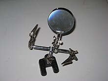
Oh, one of these are indispensable.....  :)

Use it to hold solder joints, the circuit board, many things.... available everywhere...


http://en.wikipedia.org/wiki/Helping_hand_(tool)

Many other uses besides soldering.

Get one with or without the magnifying glass.
I have both...  :loco