
Nice job Bob. :dbtu:
- Welcome to Solid State Guitar Amp Forum | DIY Guitar Amplifiers.
Solid State Guitar Amp Forum
News:
30% off all Honey Amp kits, check it out at https://store.ssguitar.com !
This section allows you to view all posts made by this member. Note that you can only see posts made in areas you currently have access to.
#1982
Amplifier Discussion / Re: New member, new old Kay solid state amp.(leaky capacitor)
August 12, 2012, 09:31:40 AM
Yeah, but teemuk, he says it's oily; that doesn't sound like flux residue to me which, as you say, goes brittle and powdery.
It reminds me very much of a radio station mixer that had been given so many sprays with some mystery cans of "instant technician" that there was oil actually running about in the bottom of the chassis (and something in the stuff had made all the cap seal bungs swell up and pop out - 'orrible), 'tho in this case it doesn't seem to have actually damaged anything except the reverb tank foam supports.
It reminds me very much of a radio station mixer that had been given so many sprays with some mystery cans of "instant technician" that there was oil actually running about in the bottom of the chassis (and something in the stuff had made all the cap seal bungs swell up and pop out - 'orrible), 'tho in this case it doesn't seem to have actually damaged anything except the reverb tank foam supports.
#1983
Amplifier Discussion / Re: New member, new old Kay solid state amp.(leaky capacitor)
August 12, 2012, 12:50:45 AM
Cute little amp. :tu:
I agree with JM, this doesn't look like cap gunk but something else that has found its way inside (misconceived attempt at cleaning with some chemical/lubricant spray, over the top pot cleaning?).
You would be amazed at the sundry residues techs find inside gear. I'd follow JM's cleaning advice rather than trying any sort of "mystery spray". I've been known to give amp innards a brush down with dishwashing liquid in warm water which is okay provided you avoid transformers and pots, rinse it all off, then (carefully/gently) dry well with blow heater, hair dryer, or just leave in a warm sunny spot.
The cap looks, from it's position, like it might be the output coupling cap, so going up in value is normally not only harmless but can make a small improvement to reliability. But if it's not actually leaking I wouldn't bother replacing it, just give everything a good clean.
Remove and renew the reverb line mounting foam.
Circuits for this general style of amp are almost unknown unless you are lucky enough to find a user trace; manufacturers simply didn't publish them, but the circuits tend to be quite generic. Output transistor type numbers?
#1984
The Newcomer's Forum / Re: Hartke B90 no sound
August 10, 2012, 10:27:51 AM
Ahh so - track blown off. Happens.
May I then suggest that you fit a couple of fuse holders somewhere between C34, +ve rail, and C35, -ve rail, and everything else?
P=150 Watts
R=8 Ohms
P=I^2*R
I^2 = P/R
I = root(P/R) = (P/R)^0.5
(150/8)^0.5 = 4.33012702 amps
So initially try say 4 amps in each rail and see how you go.
These won't prevent transistor failure, but they will help to minimise damage if that should happen again.
#1985
Amplifier Discussion / Re: ss amp, no distortion... add a 2nd volume to get gain?
August 10, 2012, 10:12:27 AM
Aww yeah, nice one Bob; high enough input impedance and a few different types of crunch and grind to play with (and I love J.O.'s name for it - DIY and save heaps). :dbtu:
#1986
Amplifier Discussion / Re: Fixing this old stereo amplifier
August 10, 2012, 10:03:31 AM
I do love to watch somebody having fun, and this one certainly sounds like it has had a good dose of the galloping silicon cancer through it - explains why it was unloved under the bench.
Vcer is generally the voltage rating you need to watch. It's unlikely to be too picky about the exact transistor types you fit, just as long as they have "enough" of what they need, voltage, current, power, and gain.
I used to work on large Variable Speed drives and it was a standing joke that expensive huge SCR's would fail to protect the fuses.
Talking of fuses, a suitable fuse in each supply rail at each amp is a good idea.
#1987
Amplifier Discussion / Re: Need advice in modifying Little Rebel's tone control
August 10, 2012, 09:41:31 AM
"Subtle" eh. And unique too - don't recall ever seeing anything quite like that before; all their own work I'd say.
As you can see the treble and middle come before the master volume, and the bass control after, so a simple conversion to some from of Fender/Marshall/Vox type passive isn't really practical.
In fact given how little there is in it you may be better off building something similar from the ground up using the tonestack you want.
What you could try playing around with is making the existing controls a bit less subtle. You can't model this in Duncan's Tone Stack Calculator since it isn't any of the common arrangements, but you could model it in LTSpice or Tina-TI (both free).
Really, the question you have to answer first is "what do you want?", more bass, more treble, more control range? Then we can have a look at which components to change in value that might give you what you want.
You should also remember that whatever speaker and enclosure you are using will have a pretty major effect on the end sound.
HTH
#1988
Amplifier Discussion / Re: ss amp, no distortion... add a 2nd volume to get gain?
August 10, 2012, 09:20:29 AM
The light bulb in the tremolo circuit is in the collector of Q13. If you follow the wiring of the tremolo depth control it should lead you to Q13 (presuming it isn't already marked on the PCB). The collector of this transistor goes to the lamp, but it will be in a light-tight container of some sort with the LDR - Light Dependent Resistor, R56.
If you don't have any voltage on the collector of Q13 it's a fair bet the lamp has failed.
This is often a small plastic tube with two wires coming out of each end and in Fender amps is often called the "roach" since it looks a bit like one. These sometimes have a brand name and type number, but more often than not you will need to do some detective work to determine a suitable replacement lamp, and a bit of creative handycraft opening it up, installing a new lamp, and making it light-tight again (I normally use black heatshrink tubing for this). Be careful not to damage the LDR in the process or you will have two lots of detective work to do.
First thing I'd do is connect the amp to a different speaker cab and see if that changes the brights.
Two things strike me about this circuit, firstly the input impedance is quite low and this will tend to dull-off any passive guitar. Secondly there is a cap at the input to the main amp, C16 0.1uF, across the audio path which may be "tone sucking".
To address the first I'd try a FET buffer between guitar and amp, or build some sort of grunge/buffer stomp box; and I'd be tempted to see what happens if the value of C13 is reduced, say to half, 0.047uF. It's possible the amp may become unstable, but it's equally possible it may be just what you want.
The On-Off-On switch is a line reversing switch peculiar to un-grounded American amps (and removed everywhere else in the world). It has the same function as reversing the plug in the wall to select the direction that gives the least noise pickup. The rest of the world uses three wires to provide a safety ground on the exposed metal parts and minimise noise pickup.
HTH
#1989
The Newcomer's Forum / Re: Hartke B90 no sound
August 09, 2012, 11:48:34 PM
> I'm getting 20mv at the speaker. C34=51v and C35= -51v.
I'm having a bit of trouble following what you are doing, but again the conditions have changed (for the better) and you are now getting very reasonable readings - plus and minus supplies, and very little DC at the speaker; this is all good. As you may have worked out, D12 is connected between the +ve supply and the output rail, and D13 is connected between the output rail and the -ve supply, making these two a handy point to find the three most important voltages.
> I was talking to a guy he said the zener D5 is most likely bad. He also advised to change all the transistors. He also noted which does sound correct, that if J5 was bad it would cut the speaker out.
Measure the voltage across the zener - measurement trumps a wild guess any day. If you have 15 volts it's okay.
Given that you now have good supplies and only 50mV across the speaker, advice such as "replace all the transistors" is, at best, let's say, not very well informed. ( :duh) This is what I call "blunderbuss" servicing and often leads to more trouble and expense than doing it properly. "Properly" means locating which component(s) are faulty, and replacing them. The blunderbuss mode is often used by people who can't actually locate faulty components, it's hit and miss, and not at all professional or reliable.
While he is right that J5 could interrupt the output, it in no way explains a) why both supplies were being loaded down to only one volt, or b) why the output rail was previously stuck at the +ve rail. This guy isn't even considering the available evidence, and when you're done you will be able to give him (better) advice.
#1990
Schematics and Layouts / Re: Randall RG100 hybrid
August 09, 2012, 11:16:09 PM #1991
The Newcomer's Forum / Re: Hartke B90 no sound
August 09, 2012, 10:40:18 AM
>Well the first test C34=1V, C35=-1V, speaker=1V.
+/- 1V supplies tell us we have a short right across.
Speaker at +1V says we have an output transistor shorted between the +ve rail and the output, i.e. Q12 and/or Q13.
>Pulled Q8, Q9, Q12, Q13 They all test good with a multi meter.
Given the measurements above it seems to me unlikely that Q12/13 are actually okay.
Firstly you need to measure the Base-Emitter and Base-Collector junctions. These should both look like diodes, between 500mV "500" and 700mV "700" forward, and open "1___" in reverse (on your multimeter diode test range). Then you need to measure the Collector-Emitter path which should be open both polarities.
>Plugged back in switched on, very dim bulb for about two seconds then it fades out.
>D12= -.384V, D13= 104.7V ?
?
Now something significant has changed because you no longer have the short between supplies, but the output rail (join of D12 and D13) is still stuck to the +ve rail, again strongly suggesting that Q12 and/or Q13 is short C-to-E.
>I guess I should test Q5 & Q11?
Yes, this is a good idea, but in any event I think you still have a shorted transistor at Q12 and/or Q13 (and it's possible that you also have Q8 and Q9 blown open).
Because this amp uses pairs of output transistors it is possible to remove only Q13 and Q9, then Q12 and Q8 to help isolate which are faulty, just as long as you don't try to drive the amp hard into a load (but you should have the speaker disconnected anyway).
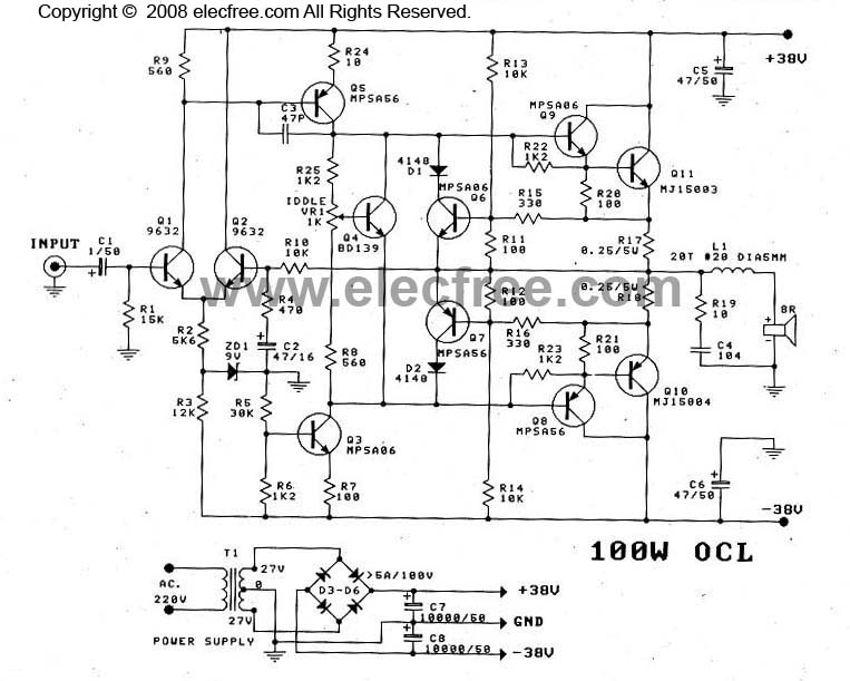
I have to say that this power amp circuit is not well drawn; it's actually quite conventional but drawn in a confusingly offset manner.
This is not identical - it only has one set of output transistors instead of two, and the initial input stages are "upside down" to yours, but this is the same general arrangement, and seeing this may help you find your way better around the Hartke circuit.
+/- 1V supplies tell us we have a short right across.
Speaker at +1V says we have an output transistor shorted between the +ve rail and the output, i.e. Q12 and/or Q13.
>Pulled Q8, Q9, Q12, Q13 They all test good with a multi meter.
Given the measurements above it seems to me unlikely that Q12/13 are actually okay.
Firstly you need to measure the Base-Emitter and Base-Collector junctions. These should both look like diodes, between 500mV "500" and 700mV "700" forward, and open "1___" in reverse (on your multimeter diode test range). Then you need to measure the Collector-Emitter path which should be open both polarities.
>Plugged back in switched on, very dim bulb for about two seconds then it fades out.
>D12= -.384V, D13= 104.7V
?Now something significant has changed because you no longer have the short between supplies, but the output rail (join of D12 and D13) is still stuck to the +ve rail, again strongly suggesting that Q12 and/or Q13 is short C-to-E.
>I guess I should test Q5 & Q11?
Yes, this is a good idea, but in any event I think you still have a shorted transistor at Q12 and/or Q13 (and it's possible that you also have Q8 and Q9 blown open).
Because this amp uses pairs of output transistors it is possible to remove only Q13 and Q9, then Q12 and Q8 to help isolate which are faulty, just as long as you don't try to drive the amp hard into a load (but you should have the speaker disconnected anyway).
I have to say that this power amp circuit is not well drawn; it's actually quite conventional but drawn in a confusingly offset manner.
This is not identical - it only has one set of output transistors instead of two, and the initial input stages are "upside down" to yours, but this is the same general arrangement, and seeing this may help you find your way better around the Hartke circuit.
#1992
Amplifier Discussion / Re: Problem with Rocktron R120C
August 09, 2012, 08:47:44 AM
Uh, okay. There are a couple of things it could be, but it's obviously a fence.
A little Aussie history is required. The first industry to really take off after white settlement was raising sheep for wool. In fact it was said for many years that Australia "rode on the sheeps' back", 'though this became progressively less true after the Second World War with a swing from primary to secondary industry.
There were a few problems running sheep in Australia, and one of them was the native wild dog, the Dingo, which not surprisingly considered a mob of sheep to be lunch on the hoof. One response to this was to construct a dog-proof fence across a huge tract of the continent and basically try and obliterate the Dingo on the "inside".
While JM's picture is titled "Dingo Fence" I'm pretty sure it isn't, because I've been through the real thing a number of times and it's a lot taller, the fence above not being tall enough to keep a Dingo out.

"Camerons Corner at the intersection of New South Wales, Queensland and South Australia. The Dingo fence seen was originally constructed to keep rabbits out, however it was later used to keep dingoes out of sheep farming areas. The fence stretches some 5,500 kilometres and is the longest fence in the world."

{the sharp eyed will notice there are two "longest fences in the world", both in different Australian States }
}
While I'm wary of any native animal that lives around tourist hot spots and picnic grounds, I have simply dossed down beside the vehicle in desert country with no worries, and even had Dingos come right into my camp for water with no problems at all. Wild pigs are a very different matter.
The fence shown in JM's post however is to meet a different problem entirely of the settlers own making - rabbits. In the early days there were "Acclimatisation Societies" that decided that the Aussie native wildlife wasn't good enough, and imported wildlife to "improve" it, mainly from England.
They liked a spot of huntin' and fishin' so they imported rabbits, foxes, carp (goldfish) and sundry other critters. The first couple of bunches of rabbits they imported were established in Geelong, not far from where I now live, but they died (or were hunted) out. So they brought in another bunch.
This time it quickly turned into a nightmare horror story - the rabbit took to Australia as rabbit heaven and in only a few years had grown to literally plague proportions across the country, adapting from the Snowy alps to the burning Simpson desert, and were rapidly crippling agriculture and eating the native animals out of house and home.
In Western Australia matters got so bad that they built a rabbit-proof fence to keep the little buggers out of the wheat growing country. It isn't clear in JM's pic but almost half the fence is underground, extending in this case I think to the left (clue; the rocks placed along the bottom).

For the time, this was a mammoth undertaking...

...but one has to understand the seriousness and scale of the problem. This gives some idea of the difference between the "outside" where the rabbits were and where this photograph was taken from, and the "inside", far side, where there were no rabbits.

It's hard to wrap your head around the fact that within a few years a few dozen rabbits had grown to several hundred million, were eating just about everything in sight, and just about everywhere was starting to look like this...

"within ten years of the introduction in 1859, rabbits had become so prevalent that two million could be shot or trapped annually without having any noticeable effect on the population. It was the fastest spread ever recorded of any mammal anywhere in the world."
Shooting was too expensive, and trapping and poison baits ineffective. Farmers would organise "drives" to push thousands into a fence corner then dozens of men would wade in and spend days plucking them out, wringing necks, and skinning for fur and meat, but still they kept coming. They became a primary source of cheap meat, felt, and there was a major export trade in their skins.

In one area of southern Australia cats were introduce as a control measure, but this only resulted in a secondary plague of cats that decimated the native wildlife.
In 1950 the CSIRO finally released Myxomatosis, a viral rodent encephalitis. Within two years 99.8% of an estimated 600 million rabbits had died from the disease, and while they developed some resistance by the late 50's would never again reach such overwhelming numbers.
"The introduction of rabbit haemorraghic disease virus RHDV (also known as rabbit calicivirus) in 1995 again reduced rabbit numbers to very low levels, with greatest impact in arid zones and lesser impact in high rainfall areas. RHDV is considered only the second successful control of a mammalian pest in the world."
While the rabbit can now be said to be under control there are still a range of other introduced pest species that aren't; horses, camels, goats, foxes, pigs, dogs, cats, deer, some birds, and sundry plant and insect species, and fish.
But the worst of all is the cane toad (Bufo marinus) introduced in 1935 to eat grubs that were damaging the sugar harvest on the Queensland coast. Not only didn't the toads eat the cane grubs, they ate anything else they could get their capacious mouths around, and their toxicity killed anything that tried to eat them. :duh

What this graphic doesn't show is that they have now spread right across the Top End (as we call it) to the far north west, hitching rides in cargo. At this time we are in a similar situation to the rabbit before "myxie" came along, except that they are effectively useless for meat or skins, toxic, even more fecund, and no fence seems capable of stopping their spread.
{now JM will introduce us to the Anaconda-proof fence :cheesy: after which normal service will be resumed}
A little Aussie history is required. The first industry to really take off after white settlement was raising sheep for wool. In fact it was said for many years that Australia "rode on the sheeps' back", 'though this became progressively less true after the Second World War with a swing from primary to secondary industry.
There were a few problems running sheep in Australia, and one of them was the native wild dog, the Dingo, which not surprisingly considered a mob of sheep to be lunch on the hoof. One response to this was to construct a dog-proof fence across a huge tract of the continent and basically try and obliterate the Dingo on the "inside".
While JM's picture is titled "Dingo Fence" I'm pretty sure it isn't, because I've been through the real thing a number of times and it's a lot taller, the fence above not being tall enough to keep a Dingo out.
"Camerons Corner at the intersection of New South Wales, Queensland and South Australia. The Dingo fence seen was originally constructed to keep rabbits out, however it was later used to keep dingoes out of sheep farming areas. The fence stretches some 5,500 kilometres and is the longest fence in the world."
{the sharp eyed will notice there are two "longest fences in the world", both in different Australian States
} While I'm wary of any native animal that lives around tourist hot spots and picnic grounds, I have simply dossed down beside the vehicle in desert country with no worries, and even had Dingos come right into my camp for water with no problems at all. Wild pigs are a very different matter.
The fence shown in JM's post however is to meet a different problem entirely of the settlers own making - rabbits. In the early days there were "Acclimatisation Societies" that decided that the Aussie native wildlife wasn't good enough, and imported wildlife to "improve" it, mainly from England.
They liked a spot of huntin' and fishin' so they imported rabbits, foxes, carp (goldfish) and sundry other critters. The first couple of bunches of rabbits they imported were established in Geelong, not far from where I now live, but they died (or were hunted) out. So they brought in another bunch.
This time it quickly turned into a nightmare horror story - the rabbit took to Australia as rabbit heaven and in only a few years had grown to literally plague proportions across the country, adapting from the Snowy alps to the burning Simpson desert, and were rapidly crippling agriculture and eating the native animals out of house and home.
In Western Australia matters got so bad that they built a rabbit-proof fence to keep the little buggers out of the wheat growing country. It isn't clear in JM's pic but almost half the fence is underground, extending in this case I think to the left (clue; the rocks placed along the bottom).
For the time, this was a mammoth undertaking...
...but one has to understand the seriousness and scale of the problem. This gives some idea of the difference between the "outside" where the rabbits were and where this photograph was taken from, and the "inside", far side, where there were no rabbits.
It's hard to wrap your head around the fact that within a few years a few dozen rabbits had grown to several hundred million, were eating just about everything in sight, and just about everywhere was starting to look like this...
"within ten years of the introduction in 1859, rabbits had become so prevalent that two million could be shot or trapped annually without having any noticeable effect on the population. It was the fastest spread ever recorded of any mammal anywhere in the world."
Shooting was too expensive, and trapping and poison baits ineffective. Farmers would organise "drives" to push thousands into a fence corner then dozens of men would wade in and spend days plucking them out, wringing necks, and skinning for fur and meat, but still they kept coming. They became a primary source of cheap meat, felt, and there was a major export trade in their skins.
In one area of southern Australia cats were introduce as a control measure, but this only resulted in a secondary plague of cats that decimated the native wildlife.
In 1950 the CSIRO finally released Myxomatosis, a viral rodent encephalitis. Within two years 99.8% of an estimated 600 million rabbits had died from the disease, and while they developed some resistance by the late 50's would never again reach such overwhelming numbers.
"The introduction of rabbit haemorraghic disease virus RHDV (also known as rabbit calicivirus) in 1995 again reduced rabbit numbers to very low levels, with greatest impact in arid zones and lesser impact in high rainfall areas. RHDV is considered only the second successful control of a mammalian pest in the world."
While the rabbit can now be said to be under control there are still a range of other introduced pest species that aren't; horses, camels, goats, foxes, pigs, dogs, cats, deer, some birds, and sundry plant and insect species, and fish.
But the worst of all is the cane toad (Bufo marinus) introduced in 1935 to eat grubs that were damaging the sugar harvest on the Queensland coast. Not only didn't the toads eat the cane grubs, they ate anything else they could get their capacious mouths around, and their toxicity killed anything that tried to eat them. :duh
What this graphic doesn't show is that they have now spread right across the Top End (as we call it) to the far north west, hitching rides in cargo. At this time we are in a similar situation to the rabbit before "myxie" came along, except that they are effectively useless for meat or skins, toxic, even more fecund, and no fence seems capable of stopping their spread.
{now JM will introduce us to the Anaconda-proof fence :cheesy: after which normal service will be resumed}
#1993
Amplifier Discussion / Re: Fixing this old stereo amplifier
August 09, 2012, 06:25:06 AM
You seem to be right on top of it. Well done. :dbtu: It's very satisfying to start out with some item of discarded junk and end up with something useful (I've just brought a couple of computers scavenged at the local tip back to life).
Power tranny - try disconnecting the output rails from the power supply filters and leaving it run idle for an hour or so. The tranny should be warm but not hot, and you should certainly be able to hold your hand on it without discomfort. If it is too hot to hold your hand on then you have a problem, however I'd give it another run isolated from the rectifier and filter caps just to be sure that it's the tranny (you could have leaky old electros, but then they would also be getting hot on idle).
The next thought is the idle current. Don't get too carried away adjusting the 2k2 idle setting 'coz it looks like it could crank the idle current up to quite a high value at the extreme settings. At the moment you look to have 0.06V/0.39ohm = 154mA which is more than a bit high. I'd guess at something more like 30 to 50mA which would be E=IR = .03*0.39 ~= 12mV - 20mV. The idea here is to start out with a low idle current (minimum voltage across Q5) and gently slide it up until you don't have any crossover distortion (which ideally needs a CRO or Noise and Distortion meter, but ears will do).
Output offset - Like JM I'm not surprised you can't set the DC offset to zero, nor do I think 50mV offset is a problem. The origin of this offset is the base current flowing out of Q1 through R1 (you'll notice the 40mV here and the 50mV at the output are almost the same). A better way to adjust this offset IMO is to suck the base current of Q1 out of that node using a very large resistor to a largish value pot across the +/- rails.
The way they have done it also changes the amp loop gain, which is not really best practice. "If its supposed to adjust the offset to zero..." is a fairly large "if". Given the 2N3055 in the output (and the position of the 10K) it is more likely it is only intended to reduce the offset to a "reasonable" value.
I have never been keen on bipolar electrolytics, so if C2 is oldish it might be a good idea to renew it.
Now R2, Q3, R3 and zener D1 form a constant current source for the Long-Tailed Pair (LTP, aka Differential pair). The current is set by R2 at the zener voltage minus the BE drop of Q3 (and if that really is a zener it's drawn upside down BTW). Taking your voltages, there is a 1.4 volt drop across the zener meaning there is around 0.7V across R2. As this voltage is reasonably constant the collector current of Q3 will be I=E/R = 0.7/3k3 = 200uA, or 0.7/2k2 = 300uA now. This is actually the tail of the Long Tail Pair, but drawn "upside-down" in PNP format it might be a bit hard to recognise as such.
And now you've got lots of volts of AC on the output - bravo! :dbtu:
Yeah, 'puters are pretty noisy audio sources.
It may also be because you have an earth loop; both the computer common is connected to mains ground and the amp common is also connected to mains ground. One thing you can try is put a simple low pass filter at the input, like a few k-ohms in series with C1 and a few pF across R1. Let's say 2k2 in series to give a 5% reduction in mid-band signal in combination with R1, then we need a cap that will give a rolloff starting about 20-25kHz. A cap that has a reactance, Xc, equal to the series resistor, 2k2, at 25kHz will give a -6dB or half voltage point at that frequency.
Xc = 1 / 2 Pi f C
or
C = 1 / 2 Pi f Xc
uF = 1/(2*Pi*25*2.2) = 0.00289373uF or around 2.7nF (ballpark, select to taste)
If the problem seems to be due to an earth loop try inserting a small resistor (47 - 220 ohms) in the common connection between the amp and computer.
HTH
#1994
Amplifier Discussion / Re: Fixing this old stereo amplifier
August 08, 2012, 12:08:10 AM
I'm beginning to wonder what you need us for, since you seem to be getting on just fine on your own (heh heh ).
In your latest pic I can't see any sign of a mica washer or other insulator under the driver transistor on the heatsink. Anodising is nominally insulating, but I certainly wouldn't depend on it.
With resistors and caps, if there is any doubt just unsolder one end, then measure. Generally speaking it's the active components that are troublesome, the passive (unless obviously broken or reduced to a charred ruin) seldom cause problems.
As you think this was a kit build I'd be inclined to go over every solder joint too, just to be sure they are properly made.
Getting the other channel going if you can is a good idea (but I'd use the limiting lamp on such an unknown quantity); often the nice thing about servicing stereo amps is that you have a going channel alongside the dead one to compare. Good luck. :tu:
).In your latest pic I can't see any sign of a mica washer or other insulator under the driver transistor on the heatsink. Anodising is nominally insulating, but I certainly wouldn't depend on it.
With resistors and caps, if there is any doubt just unsolder one end, then measure. Generally speaking it's the active components that are troublesome, the passive (unless obviously broken or reduced to a charred ruin) seldom cause problems.
As you think this was a kit build I'd be inclined to go over every solder joint too, just to be sure they are properly made.
Getting the other channel going if you can is a good idea (but I'd use the limiting lamp on such an unknown quantity); often the nice thing about servicing stereo amps is that you have a going channel alongside the dead one to compare. Good luck. :tu: