Menu

Show posts

This section allows you to view all posts made by this member. Note that you can only see posts made in areas you currently have access to.

Show posts Menu

Messages - Roly

#181
Quote from: joecool85For every 10db gain (double perceived volume) you need a 10x multiplication of wattage.  So a 100watt amp is only twice as loud as a 10watt amp.

...


Speaker sens. (1dB/W@1m) Required power (watts)
104db1
101db2
98db3
95db6
92db12
89db24
86db48
83db96
80db191
77db382
See: Watts vs Volume (db)

Quote from: http://www.gcaudio.com/resources/howtos/voltageloudness.html


dB ChangeVoltagePowerLoudness
31.4X2X1.23X
62.04.01.52
103.16102
20101004
4010010,00016

#182
Amplifier Discussion / Re: Marshall Valvestate 8100
March 19, 2015, 08:37:52 AM
And my paying more attention would have helped.   :-[

Okay, bum rap, that was off the screen in the x2 magnification I was looking at it.  Still, they did manage to get the diodes the right way around this time.
#183
They got it in there, therefore you can get it out.

Quote from: frankfurts
I think I may have found a problem with the input jack.

...

I found my problem.  My 1M grounding resistor (R1) is short circuited.

Now hold on a minute here.

I assume we are talking about R1/1Meg across the input socket?

A) you are aware that this socket has a shorting contact in parallel with R1, and that if an open lead is not plugged in to the socket the input is shorted?


B) Shorted 1Meg resistor is quite unusual in itself, and cause for a few moment pause.  Is it burned up?  If so, how much voltage would it take coming in the input to fry a resistor of this wattage like this?

If this is not a mistake but a real failure, then it has profound implications for the components surrounding, not least the first op-amp.

But this now seems to be working okay now you say?

My intuition is that this diagnosis needs to be revisited in more detail.   8|


If this socket solders directly onto the PCB, have you carefully gone over its solder connections with a lens and a bright light?  With modern gear this is a primary fault zone.
#184
{you're evil  8| }


Quote from: EnzoThey want to experiment on your amp.

Yup, and I don't think that's a good idea either.   ::)


Borrow and try some other cabs/amps.  If he wants to still use the Peavey as a front end with preamp, EQ and Fx then you can always patch the Fx Send to the Fx Return (or input) on a slave under test.

I'd be on the lookout for a sealed 2x12 that you can borrow to try out, either with its own head, or drive cobbled from the Peavey (but be very careful of output shorts - not for even a moment or you may kill the output stage.)


As a generality the bandwidth of a 12-inch will be slightly lower set than a 10-inch, go a little lower in frequency but also not quite as high, but as Enzo implies, there are exceptions to every speaker "rule" and the driver model manufacturers spec sheet is the final word.

The raw power rating of a driver is a measure of its robustness, and not much else.  While this relates to suspension and cone toughness, in high power drivers these days it mainly relates to how well the voice coil can get rid of waste heat before melting.

The sensitivity is an important parameter that often gets overlooked.  This is the number of dBSPL that the driver can deliver for one watt in, at 1m range on the centreline (in an anechoic environment, such as a large paddock.  ).  How good it is at converting electricity into sound.  This is given in dB/W and the higher the better.  95dB/W is pretty poor, 100dB/W is good, and 105dB/W is very good, so being a logarithmic measure it is a very sensitive function, every extra dB counts.


Why a "sealed 2x12"?

Keyword: "fullness".  Experience shows that a difference between an open-back combo and a sealed cab is that the combo tends to be brighter, and the sealed cab has less tops but more "body".

There are all sorts of reasons for this, back radiation and such, but basically an open-back combo enclosure has a passband that looks like the Swiss Alps, and that it has a fairly high low-end cutoff.

A sealed enclosure by contrast generally has a pretty smooth passband response, and will typically go a bit lower before it starts to roll off.

My last unsupported assertion is that more cone area is good.  Take just about any audio toy, 1W ciggi box amp, MP3 pod, &c&c, and hook it up to a big guitar cab like a Marshall stack, and be astonished.

{When I was churning out hand-held AM radios they sounded awful, until you plugged the bench speaker box into the headphone socket, and you had very respectable full bandwidth reproduction.  It's just that the inbuilt 2" speaker and tiny case just weren't up it.}
#185
Quote from: js1970I reset the bias like you said. At idle btw the bases of Q309/310 I have 2.540V and trending down as it warmed up. Also, btw the TPs, I started at 24mV which dropped steadily to settle about 16 mV +/- 1mV.
   These measurements were taken over 30 min at idle.

This all looks quite good indeed.  The bias may be a bit over-compensated for temperature, but that's not particularly abnormal and far better that than going into thermal runaway.


R317
What we've got here is a differential or Long Tailed Pair, Q304 and Q305 (common tail above, loads below).  The Q305 side is the drive for the power amp, the R317 side its differential partner.  Now what they have done is run these two LTP loads into a current mirror, Q306 and Q307, and if you suspect that something is amiss I would have these transistors out for checking (however it is not uncommon for power resistors to run too hot to touch.)

{Note that the preceding stage is also a LTP but the other way up, and a current mirror has been used to set the tail current here.}

To be specific: on the circuit I'm looking at <Ha3500.pdf> R317 is a 15k/2W in the collector of Q304.

83v and 43V on 15k

I = E/R
(83-43)/15 = 2.66666667mA

P = E * I

(83-43) * 2.66666667 = 106.66666680mW

This seems very reasonable, a tenth of a watt ain't much, so something doesn't fit here, your observation doesn't make sense with my circuit.
#186
Amplifier Discussion / Re: Marshall Valvestate 8100
March 19, 2015, 12:39:26 AM
Thank you Enzo, that is so much easier on my poor old eyes.

{And here we note that D4 and D5 are drawn the right way around - but now they have forgotten the values for R97 and R117!  (sigh)   "No circuit is without errors".}

When it comes to repairing anything I have observed that commonsense and a good set of eyeballs can take you far - i.e. paying attention helps a lot.
#187
Gawd, simple and well stated question that opens a real can of worms.


Quote from: PoorOtis...something about "Fullness"...
...
Can a new speaker in a larger size make that much difference in the amps abilities or over-all tone??

Well, ya know, that depends, ... but mainly ... um ... "bollocks".

I suspect that this is more about trying stuff and seeing what happens, and you may feel inclined to indulge this a bit, but as for "tone"...


So what has it got in it now?  A 10-inch?

A great deal of the tonality of an amp is tied to the case/speaker enclosure.  The combo style is practical, but normally quite a compromise as far as being a speaker cabinet is concerned.

Rather than changing the speaker you could borrow some other speaker cabs and try them out with the amp at practice sessions.  "Fullness" suggests to me a pair of 12's in a sealed enclosure.
#188
Amplifier Discussion / Re: Marshall Valvestate 8100
March 18, 2015, 01:34:34 PM
Quote from: HawkI feel like I should be paying you guys!

Insert Card Here...


Quote from: HawkWhen you say a proxy do you mean I can treat as a gauge for  current flow? With multimeter check for high voltage, therefore high current, low voltage low current?

Exactly.  Current, voltage and resistance are locked together via Ohms Law.

Your older moving coil or d'Arsonval type meter actually responds to current, so voltage must be implied by the large resistance in series with the meter.

Modern digital meters typically only measure voltage, so current must be implied from a small resistance in parallel with the meter.

Similarly with resistance measurement a moving coil meter puts a fixed voltage across the terminals and measures the resulting current, while a DMM applies a constant current to the terminals and measures the resulting voltage.

"E equals I multiplied by R" said Georg Simon Ohm - and you can bet your life on it.


Quote from: HawkWhat is the purpose of D4,D5, what is their function in the current limiting circuit? To take only the pos/neg half of the signal? D5--neg. half, D6, pos. half? Both turning on at.7v?

Ohdearohdearohdear.  On the (fuzzy) circuit I'm looking at <8080-pwr.gif> D4 and D5 are drawn the wrong way around!  Both are supposed to be pointing downwards, not upwards - as drawn the protection won't work.

They are there to protect the associated clamp transistor from being reversed biased on the "other" half cycle.


Quote from: HawkWhat is the purpose of TR9, R73,R74, TR4, TR7, C49, C47?

See;
http://www.ssguitar.com/index.php?topic=3592.msg28780#msg28780


Quote from: HawkAlso, a buddy is bringing over an old tube radio he wants me to fix for him. Can anyone suggest a good forum to ask questions?

Do not twiddle any of the many presets - these require special equipment to set.

Basic superheterodyne radio receiver and waveforms.


Most electronics faults are common, simple, and fairly easy to fix, however there are some considerable differences between an audio amplifier and a radio receiver (I assume AM only), and a bunch of different concepts and techniques that are required.  If the problem turns out to be simple, e.g. a valve not lighting up, or in the audio section, then you're away, but ahead of the audio section there are a number of other stages;typically an Intermediate Frequency amplifier with tuned LC loads working at 455kHz, before that a Radio Frequency mixer stage, a Local Oscillator running around a megahertz, and perhaps a RF preamp stage (as above).

Radios made for the consumer market have a long history and are not helped by the commercial competition which saw very many designs with all sorts of odd circuit arrangements with the aim of getting maximum performance with minimum cost - and some of the worst cost cutting would make your eyes water.  There were also Patent wars where manufacturers did things differently because they had to, or pay.


By all means have a look (run a mile if it's an AC/DC set, they are killers), check that the chassis is grounded for your safety, then just the usual stuff, valves lighting up?  HT voltage?  Any signs of life in the audio?  Can we see signals anywhere (for which a CRO is very handy indeed)?

Same old story, signal flows from antenna connection to speaker, how far is it getting, and why not?

But having said that, don't be surprised if you very suddenly find yourself well out of your depth.

My first job in electronics was production line servicing AM radios, so I have repaired literally thousands.  Most service techs get to be expert in one or two particular fields, get to know radios, TV's, VCR's, cellphones, laptops, or microwaves and other kitchen appliances, &c&c, and often not a lot outside their area.  I have covered a lot of fields; design, production, industrial, bio-med, off-grid power, theater/film, AM/FM/UHF-TV broadcast, &c&c, and tried to be an "electronics generalist" so the list of things I've worked on (and normally fixed) is huge.

I'm quite happy to hand-hold you through a radio repair, but you need to clearly understand that this opens a whole new bag of concepts (and frankly, I don't think is possible via forum or email if the problem is in the IF or RF stages).

Now we warn folks that building electronics projects can be highly additive, but we don't often mention that if you want to be any good at electronics you had better be prepared for a lifetime of reading, study, and a bit of research (even if you are only ever going to do guitar amps).

You want a flying start? - then NEETS, here;
http://www.fcctests.com/neets/neets.htm

A good grounding in Module 1 is vital, but after that you can just browse Modules as the need arises ('tho you may well find that Module 17, Radio-Frequency Communications Principles, first needs an understanding of Module 12, Modulation Principles, and perhaps others).


Yagotta stay curious 'bout stuff.
#189
Quote from: js1970l can't help but wonder if maybe R321 or R317 has gone bad

Well don't just stand there muttering "short circuit" lad - lengthen it!  Out with your multimeter and prove the point to your satisfaction one way or the other.


Quote from: js1970I ran the amp at full mains ,only to have it overheat. After about 15 min, the protection relay clicked open, and the heatsink was hot to touch.

I assume this was at or near idle, not fully driven.  If 15 mins of full drive opens the thermal cutout then I wouldn't be impressed, but I also wouldn't be too worried (and I'd fit a fan).

But the thermal tripping after 15 mins only on idle is a real worry.

It could be that the idle bias is set too high, but it certainly seems to be that the thermal compensation, thermistor TH302, which is supposed to reduce the bias as the rig gets hot, isn't doing it job.

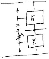
This thermal compensation is more normally a couple of forward-biased diodes.  As they get hot the idea is that their forward voltage drop falls in step with the B-E junctions of the drivers and OP transistors, and ideally the bias current remains rock steady from freezing to roasting.  Ideally.

In more professional rigs you see these compensation components actually mounted on the heatsink, which makes very good sense since that is what they are supposed to be responding to/measuring.

In consumer stereos they are almost always fitted on the PCB nearby on the assumption that, given the amplifier duty, they will be about the same temperature.  In high power rigs this is not a safe assumption, and simply having it out of its case can effectively decouple the sensor from the thing it is supposed to be sensing.

Now you previously observed that heating the thermistor with your fingers caused the bias current to drop, so that suggests that the circuit itself is working properly, just that it isn't having enough effect to hold the bias under control.


However;
Quote from: js1970the protection relay clicked

All this does is look for standing DC on the output, it isn't the thermal cutout.

So I'm wondering; you previously set the bias current, but wasn't that with a Limiting Lamp in series?

Perhaps you should back the bias off, connect the amp direct to mains, then carefully re-set the bias to the correct value on full mains voltage, and closely observe it as the rig warms up.

Let's see where that leaves us.
#190
Amplifier Discussion / Re: Marshall Valvestate 8100
March 17, 2015, 01:04:27 AM
Quote from: HawkI'll soon discover what I can and can't do with amps

One of the great joys of my life is opening things that were never intended to be opened, generally while repairing something that was never intended to be repaired.

I fancy that I can hear, somewhere far across a distant sea, some dude in a suit yelling in pain "You're killing me here!  THROW IT OUT!  BUY A NEW ONE!  MAKE ME RICH!".  And I thumb my nose - I'm on the side of the planet here; repair, reuse, recycle.   :dbtu:


Quote from: Hawkthen I played my guitar and measured the voltage across the resistor and measured it referenced to ground

The voltage across the emitter resistor is a proxy for the current passing through it and the transistor.  The voltage to ground is effectively the output voltage, whichever side of the emitter resistor you measure it.

We basically have two situations, static or idle where all the voltages and currents are steady and a multimeter is the most suitable measuring instrument; and dynamic or being driven with signal when the CRO is really a more suitable instrument than a multimeter.


Here are two popular forms of output stage current limiting;

(Note that the output stage consists only of Q2 and the 0.2r emitter resistor, everything else is protection).

Like Enzo, to me that discussion looks like determining at what current the protection would cut in.

To find the ballpark: assuming a 50W amp with +/-35V rails into an 8 ohm load.  Now we know all these numbers are rubbery and subject to a lot of "yeah, but...", however to a first approximation we can estimate the (lossless) peak output current to be;

I = Vrail/Rload

35/8 = 4.375 amps peak.  This is the minimum must-not-operate current because it is within specs.

A typical emitter resistor is 0.22 ohms, so the resulting peak voltage across the emitter resistor will be;

E = Ipk * Re

4.375 * 0.22 = 0.96 volts peak (or not quite a volt peak).

Now as Enzo said, the "given" value for the Base-Emitter cut-in voltage for a silicone transistor is "0.6V" (+/-0.1V in reality).  If we simply connected the protection transistor Base to the emitter resistor it would start to conduct (and clamp the drive into the power transistor) too early, limiting output peaks that are within ratings.  We actually want it to limit for some current above the allowable peak of 4.375 amps, and this might represent a voltage almost double, say 1.0 to 1.2 volts, and this is where the (roughly 2:1) divider across the emitter resistor comes in.

The question being addressed in the other forum is, "at what current does this circuit actually limit?" and the currents quoted look to be just about what I would expect;

QuoteIt will result in 1.92 volts across R118 , this will give a limit of 1.92 / 0.33 = 5.82 A
For R96 it will result in 2.14 Volts , this will give a limit of 2.14 / 0.33 = 6.48 A.

So the +ve and -ve peak current limits are a bit different, but outside the normal working peak current of 4.375 A, and still well within the capabilities of modern transistors.  What has been prevented is that very high current spike, tens of amps when the output gets shorted under full drive, that kills the output transistors.

So this is worked backwards, starting with the Vbe ("0.6V" nominal) of the protection transistor, multiplied by the resistive divider, giving a trigger voltage across the emitter resistor, and finally the current for that trigger voltage.


The only time there should be any activity in these protection circuits is when the amp is being driven into a load of lower resistance than it was designed to tolerate, e.g. a 4 ohm cab on an 8 ohm minimum.


{Sidebar: on the cct I have the OP transistors are shown with double emitter arrows.  This means that these devices are Darlington transistors;


... which have inbuilt driver transistors, and thus their Vbe is double normal, around "1.2V" nominal.}

#191
Amplifier Discussion / Re: Marshall Valvestate 8100
March 16, 2015, 12:31:02 PM
Quote from: Hawkis there a way to have the circuit board out of the amp with the appropriate wires still connected so that I can test components with the amp in it's "on" state?

Every one is different.

I've worked on a huge range of equipment, and how easy it is to faultfind and repair covers a vast range from bloody wonderful to bloody appalling.

There is a special case of Murphy's Law which states that "an intermittent fault will only occur when the last of 24 retaining bolts are tightened down".  Well I once had exactly that with an industrial controller in a big flameproof box.


The very best:

A Philips car cassette player in for service.  Open lid and find a stack of three large PCB's.  Single multipole connector on one corner - unplug.  Now the whole lot swings up out of the mechanism and flat over the back, then the rest unfolds to the right, and the final layer folds forward and the connector can again be plugged in and the whole thing run while spread out flat on the bench.  Cunning design.


One of the very worst (and there are very many more contestants for this award, the world if full of "cost-effective" stinkers*):

Early Yamaha 8-channel digital mixing desk with flying faders.  Now generally speaking Yamaha stuff is pretty good, I've got a fair bit and it all works and is built well.  But there are exceptions and this mixer was an extreme one.

The flying faders where now slipping a lot, but investigation suggested that it was a design problem that couldn't be fixed.

One of the inputs was dead which turned out to be a dead A/D converter module which was unobtainable.

The proximate reason for it coming in was that it had started to forget its presets, and I suspected a dying backup battery.

When I opened the mixer up I found several large PCB's in layers about an inch apart, and the lot laced through with many un-insulated tinned copper wire links scattered all over the boards and running from top to bottom.  I did locate the backup battery but it was soldered in to the centre of one of the middle layer boards - simply impossible to access without seriously demolishing the PCB assembly.

{* saw a very impressive looking iPod dock/amp/speakers junked after less than a year.  Inside it was boards and modules just indifferently glued to the inside of the fiberboard case, as crude and rough and sloppy as one could imagine.)


Every time I open up some item of gear I can tell what sort of people designed it and put it together, and what sort of attitudes they have to the planet and their fellow humans.

With guitar amps, Fenders the component boards are so wired down you have no hope of swing one up, but other amps, I'm thinking Overreem, all the connections to the boards come off one end - a few screws and presto, you can work on the board hot, standing on end.

We had two rack amps in the PA, a New Zealand Perreaux, and an American CueTek.  The most significant difference between them was that the Perreaux had a removable lid and bottom, leaving the amp totally accessible, while the CueTek was poured into a U-channel case and you couldn't get at anything.

A lot of gear is designed to be manufactured.  It is not designed to be disassembled.  At all.  Ever.  Much less repaired.

A large part of my life has been figuring out how to get assemblies open, particularly stuff that wasn't intended to be opened again.
#192
Amplifier Discussion / Re: Frontman 25R mods
March 16, 2015, 12:39:24 AM
I don't have any specific ideas about which 12-inch driver to put in the box, but I would suggest going for between 50-70L capacity (you can always pad it away, but you can't add it if you don't have it to begin with); and driver efficiency in dB/W being very important, particularly if you want to actually gig a small (15W amp) in small venues, bars, pubs, clubs...

#193
Quote from: js1970I'm reluctant to go full mains.
    Why does the bias drop like that with increased signal?
    You said the bias is a static setting, which i take to mean it is set  for the power amp to run most efficiently to amplify a signal, but with the signal effectively stealing voltage from this setting, how can the power amp be working sufficiently, let alone efficiently?

Uh huh, this is about what I'd expect.

Limiting lamp, increased signal, increased current, supply voltage droops, bias circuit responds.

Quote from: js1970I ran the hartke through a 100W floodlight bulb

In my workshop if that didn't produce smoke I'd call it "fixed".   :dbtu:


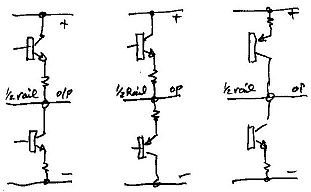
To recap; the bias is required because the transistors in the top and bottom of the "totem poll";


... don't start to turn on at zero volts but about 0.6 volts, making a deadband of around 1.2 volts while the signal crosses zero.


This is extreme Class-B and produces horrible crossover distortion.


To eliminate this the output bases are driven with an inbuilt bias between them to bring both to the edge of conduction while idle, and to ensure that there is a smooth change over of conduction between them at signal zero crossings.


Away from zero the bias has little effect since one or other of the output transistors will be in major conduction and the other off, even 'tho "biassed".


{if you really want to get into the nitty-gritty you need to look inside the devices, at their models. 


Particularly with power devices, you don't just have an "ideal" transistor.  In this case you need to consider that each electrode has its own parasitic resistance in series, so that when the base current goes up the actual pin voltage will be somewhat higher than the theoretical B-E voltage of the ideal (internal) device.  But you can't actually get to that, you have to deal with the real-world at the leads, and that includes electrode bulk resistance that gets significant under some conditions.

Similarly a power FET may look like an ideal switch under DC conditions, but the gate has a huge parasitic capacitance, so if you want to run one in Class-D at 100kHz clock rate you have one hell of a problem driving that gate capacitance fast enough so it doesn't get horribly inefficient and lossy.

Water is wet, rocks are hard, and devices have real-world limitations you just have to work around.}

HTH
#194
Amplifier Discussion / Re: Frontman 25R mods
March 15, 2015, 11:18:39 PM
Hi, Alex318798, welcome.  I'm in Victoria, Australia.


Lots of good advice in this thread.   :dbtu:

Generally; the smaller the amp is, the more important the speaker and cab is.  Take any of the micro-amps, 1-10 watts, or pod/MP3 player &c&c, plug it in to a genuine guitar cab and the improvement is often astonishing, not loud maybe, but richer and fuller.


TC5 asked me a specific question back in May that I missed.

Quote from: TC5 on May 20, 2014, 08:21:30 AM
this little guy gives me the best clean tone. Boggles the mind how the cheapest amp sounds best (to me anyway)!...

...

So I gather that this passage below from your earlier post would not apply to the Frontman, and there is no op amp in it that can be upgraded to lower it's noise floor?

Quote from: Roly on February 09, 2014, 03:25:34 AM
Originally the preamp gain came from "low noise" BC109C's, but still had quite a significant and audible noise floor.

The pre I built to replace it was nominally the same except it used LM833's (at a buck-and-a-half a pair) for the gain.

The second shock is that it is now so quiet you can't tell if it's turned on without looking at the pilot light.  {It can be a little unnerving on stage actually because now there is no audible clue that you have left the gain really cranked and are just about to give everyone an unintended blow-wave.}


Simplicity vs. Complexity.

Some of the most highly coveted amps here are vintage classics that have very basic circuits, simple and effective.

Fender 5F2

Very buildable early amp clone.

Contrast these with any of the modern generation of "cyber-amp" with a built-in Fx box (pioneered by the very same company! F****r).

...I digress...

The cct I have shows TL072's in the pre's.  These are good, but following the maxim that "the first stage sets the noise floor", so a lower noise dual such as an LM833 could be just dropped in ad-lib to possible advantage - YMMV.

After that it becomes a bit of a research project - what, exactly, is this residual noise, and it's source (in this amp, not a fault but a design limit (so we are now into re-designing the amp))?


Quote from: Alex318798And de cabinet can be opened or should be closed?

It could be either.  Open back tends to be brighter, closed back fuller, but a bit duller.

Quote from: Alex318798this amplifier have.. High overtone... sound very acute (treeble) in higher volume

As you seem to have too much treble, too many tops, I would go with the sealed style with a large internal volume, a 12-inch in 50 Litres minimum, and this would tend to bring the top and bottom back into balance more, a little less treble, a bit fuller bottom end to compete.
#195
Hi snapcracklepop, welcome.


Nice amp at any price, but $50 is a real score.   :dbtu: