Menu

Show posts

This section allows you to view all posts made by this member. Note that you can only see posts made in areas you currently have access to.

Show posts Menu

Messages - teemuk

#121
QuoteI remember reading that some SS Vox Amps where made in the triumph factory.

Yep, they were a subcontractor to the company that owned the Vox trademarks. They designed a few models and manufactured some other. If I remeber right they designed the 7 and 4 -series hybrid amps and the PC board AC30's.

QuoteAnyway I just found this; http://vintageamps.com/plexiboard/viewtopic.php?f=10&t=78014
Pics are gone and I don't know if it refers to SS.
I was going to post that when JM Fahey asked for the schematics. I have those schematics saved somewhere but I have an ungodly pile of CR-ROMs full of schematics in no sorted order and it takes a good hour to start browsing through the "suspects".
And for what...? A schematic of a generic solid-state power amp with generic current feedback scheme. All you knowing what the talk is about know what to expect. There's really nothing to see; the only remarkable feat is how early they did it.
#122
QuoteTriumph??? Jordan???

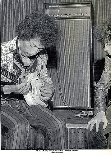
Well, at least those Triumph amps were the main amps in Keith Richards' rig (not to mention the company built amps for Jennings/Vox) and I'm sure some other people were acquinted with them too...


I'd imagine Marshall was more than willing to do some some research with whom and what they compete with.
#123
I think it really falls down to how each individual perceives certain characteristics in tone.

Personally, I hear the effect only as slight boost at low and high frequencies. I usually have to struggle to hear it as well.

Then again, I've encountered people who say it makes an astounding difference. Last one saying so wasn't even talking about current feedback per se but about differences of running a 100% tube amp to either purely resistive dummy load, or to a dummy load that mimicked speaker impedance. The effect / difference is essentially the same.

For him the resistive dummy load was too sterile, the reactive was "squishy" and responding to playing dynamics making a "Night/Day" difference. Personally, I had to struggle to hear the slight difference. ...as usual.

I once angried someone by stating that only thing the "Reactance" control in his Rocktron Velocity did was basically equivalent to diming bass and treble controls of a generic HiFi -style EQ - nothing else. He got mad insisting the control turned his amp to touch-responsive dynamic setup that sagged like a real tube amp.  ...all that from a generic boost of low and high frequencies. The control didn't even try to mimic the unique response of a poorly damped amp driving a loudspeaker. It just introduced a basic treble and bass boost.

It's all in how you perceive things, and perceiving can be based 99% on imagination and 1% on "real" auditory information. It's always more or less subjective. Therefore I wouldn't jump to definite conclusions too quickly. Yes, objectively viewed the damping barely has a slight effect on frequency response... but so far I never encountered anyone who would sense things 100% "objectively".
#124
The utilization of current feedback - first in positive format - to alter output impedance and damping characteristics dates back to about early 1950's and tube technology. At first it was used to straighten out the amplifier's response. There were several articles about the invention in various magazines of the art and eventually the design was even patented by a certain Bogen designer who was also responsible for writing various magazine articles about the idea.

Aside a few applications the idea never caught much fire in a large scale. From that point on the scheme was used now and then, in guitar amps at least Seymour Duncan utilised it. They pretty much carbon copied a certain magazine circuit.

Current feedback in negative phase form, to "unstraighten" the response of a solid-state amp, was introduced already in 1965 in Triumph's solid-state amps. That's at least the first reference I've seen of it so far. From then on various manufacturers have claimed they have "invented" it and that it is something entirely new, groundbreaking technology. They usually have their own market-appealing pseudoscientific name for it - likely because the guys who market these amps realize it's more wortwhile to give an impression that the amplifiers feature some super exciting proprietary feature than to simply state that their amplifiers are copying the exact same idea as 100 other amp makers.

A short list of where I've "first" seen negative current feedback used to mimick tube amps is somewhat along these lines:

- Triumph amps (1965)
- Ampeg SST/SBT series (1969)
- Jordan 120 & 140 (1970)
- Polytone amps (1975)
- Rickenbacker TR series (1977)
- Randall amps (ca. 1977)
- Risson amps (ca. 1978)
- Barcus-Berry amps (1979)
- Dynacord GS-series (1980)
- Peavey (ca. 1980, possibly earlier)
- Fender "CIP" (1981)
- The famous Carver's "Challenge" to HiFi magazines and following series of amplifiers (1985)
- Crate G-series amps (ca. 1986, possibly earlier)
- Rickenbacker RG-series (1989)
- Rocktron (1991)
- Marshall Valvestate series (1991)

...so at the point "Valvestate" amps appeared the technology was already well-established and pretty much a standard feature in guitar amps. If I remember right, someone tipped me of a german book about transistor guitar amps written in early 1980's and the book already discussed the principle. The patent of Dynacord's tube emulation from 1980 just briefly mentions the featured current feedback, and basically makes no big deal about it since at the point everyone making guitar amps already seemed to use the scheme. And like J M Fahey states, it can even be discussed in good analog electronics reference books. So, wake me up if you can actually point a reference prior 1965 of "inventing" this thing.

Did Marshall "invent" it? Well, obviously not. Were they aware of that type of circuit? Most definitely, those guys ain't stupid. Would their amps have sold like hot cakes without the "Valvestate" hype...? Hell No! Like said, those guys ain't stupid.
#125
I wouldn't advice going overboard with the capacitance. Too much of it and the inrush will begin to blow fuses. Use caps that have equal or higher voltage rating than the caps you are replacing. For capacitance, get something that's in the ballpark of the old part.

If the old one was, say 500uF, don't use a 1000uF cap but maybe a 470uF, 520uF, or 560uF.

As for unobtanium germanium transistors. If they die replace with silicon and reconfigure the bias circuit. You probably won't notice much difference except for a huge improvement in reliability. R.G. Keen has written some good stuff about this issue concerning Thomas Organ solid-state Vox amplifiers. The good news: The information is for most parts interchangeable since you likely find a very similar design from these amps.

Schematics and layouts..? Heck, if you really need them just spend a few hours to sketch them out. With these kinds of amps it's still humanly possible without a microscope and without having to spend weeks into the process. If you choose to take that path then post the sketches here (or to the Internet in general) so that in the future there actually will be some information and technical documentary about these amps to help other guys like you.
#126
I had a few notes about them in my collection. They were a product of Stereson Amplifiers and Accessories from Clearwater, Florida. Made from late 1960's to maybe mid 1970's. Not fisrt solid-state amps by a long shot but in the second generation. At least some of the amplifiers they made tried to ride with the Kustom fame, copying their "tuck-n-roll" upholstery.
#127
Amplifier Discussion / Re: line level xlr output
May 06, 2012, 05:09:12 AM
Yes.
#128
Amplifier Discussion / Re: Light Bulb Limiter
April 30, 2012, 02:10:29 PM
Quoteswitch mode power supplies

Not a good idea. Those things are often self regulating so they kinda hate everything that reduces the mains input voltage... The results might be catastrophic or the internal protection circuit might just disable switching due to low voltage condition or something.

Light bublb limiter might work with some SMPS but probably the odds are against it most of the times. Therefore I don't really recommend trying.
#129
QuoteSo I am thinking to put the sanding machine on duty and remove the carpet cover, and then apply some kind of wood protective lacquer to the cabinet. Any suggestions?

First make sure that there actually is any sort of wood layer to lacquer. Even if it was a hardwood / plywood cab there will still be a lot of work to sand off all glue residues, not to mention to make the surface finish top notch so that the lacquer won't reveal pretty much all dents, scratches, etc.

Personally, I'd just recover the cab or leave it as is. It doesn't look half that bad in the photos and if the amp already sounds great why care too much about the looks. It's just a basic workhorse amp, not a supermodel.
#130
Amplifier Discussion / Re: Baldwin Professional C1
April 14, 2012, 05:43:47 PM
The rectifier diode orientation should instantly reveal the required cap orientation.
#131
Tubes and Hybrids / Re: Mosvalves?
April 01, 2012, 06:37:40 AM
They are great amps, but be aware that they probably are not the best choice if you look for features like headroom or transparency because the MOSvalves are designed to colour the sound by having a somewhat non-linear response and especially to softclip the MOSFET outputs if driven harder. The latter feature will inherently limit the clean headroom, though it's something that certain people do look for from a power amp. They are not like your average transparent PA, which is either a good or bad thing, depending on each person's individual taste and preferences.

The rule of thumb is: if you want headroom then always choose the highest output power. Simple physics. Can't go wrong with that. Do also note that headroom translates to things like more authoritive bass response and overall signal clarity but it does not neccessarily equal greater perceived loudness or ability to cut through the bandmix any better. A low power amp outputting mid-range oriented signal that is compressed by clipping may sound far louder than a higher power amp that operates on a wider bandwidth and also reproduces all the signal peaks accurately instead of clipping them. The difference of headroom levels is often more a "feel" and overall "tone" thing than a loudness thing.
#132
Amplifier Discussion / Re: Transformer issues.
March 11, 2012, 06:07:58 AM
Your best bet is to discard that rectifier setup; it needs two isolated secondary windings, which your transformer doesn't have.

Use only a single rectifier like suggested in former posts.
#133
It's an opinion divider: Some hear enormous effects from the non-linear response the high output impedance creates when you pair it up to a reactive speaker load, some only hear a slight bass and treble boost. I'm in the latter category myself but for some people the effects of that scheme seem to make a ton of difference. In either case, the scheme is likely found from 90% of today's solid-state guitar amps so it must mean something.
#134
I doubt they made many changes from II.

First of all, the transformers are naturally different for European and US version of the amps.
The secondary is either:

15.2VAC x 2, 7.2VAC (amps with TDA2030)
16.5VAC x 2, 7.2VAC (amps with TDA2050)

Anyway, the power amp chip is most likely the same, either TDA2030 or TDA2050, so a quick math and referring to datasheet should tell an approximate of the rail voltage the chip requires to produce the rated output power to rated nominal load. Look at the filter caps of this supply; what voltage are they rated at? Few volts down from that is a good bet. I doubt the rev III amps will have any difference to values quoted in the service manual of rev II.

This higher voltage power supply, powering the chip, is bipolar so it (most likely) uses either both red or both blue wires and the black wire as the center tap connection. Less than few minutes of actually looking at the circuit boards should indicate what wire connects where. Which colour wires connect the rectifier diodes connecting to the filter caps with highest voltage ratings (likely biggest caps on the board, likely rated about 2200uF / 25V)? Does black wire connect to the node in between the caps?

That power supply is brought down to +- 9VDC with regulators and it feeds the analog circuitry. These regulators are likely discrete.

The second power supply is for lower voltage and of "single supply" type. Both wires from the transformer will therefore again connect to rectifier diodes (different diodes in this case, naturally) but there will be no center tap connection. Again, quick look at the board should reveal whether its the blue or red wires going to the rectifier diodes of this power supply section. You can identify them because the rectifier's output will connect on only one big filter cap (likely rated about 3300uF/16V). I don't know what voltage that power supply will have (about 10 - 9VDC) but it will be powering the footswitch and is brought down to +3.3VDC for digital circuitry with a regulator, likely a LM317. Again, should be pretty easy to locate and verify the colour coding used.
#135
Is it LOUD hum, everything else pretty much mute? If yes, it could be a blown power output. A light bulb limiter would instantly reveal if there's excessive current draw.