Menu

Show posts

This section allows you to view all posts made by this member. Note that you can only see posts made in areas you currently have access to.

Show posts Menu

Messages - teemuk

#106
Quoteone of the more curious "features" is that the gain of the OP stage is a sensitive function of the volume control position.

Well... It is an inverting amp so the gain is basically defined as Rf / Rin.
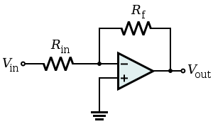


Needless to say, Rin in this particular design isn't constant but depends mainly on potentiometer's setting. With volume up all the way Rin is - in theory - zero and the gain jumps through the roof. I'm not surprised that the amp also becomes somewhat unstable at that point.

QuoteRed Circuits are TERRIBLE  , and that's being too kind.

This man speaks the truth. Crappy, inreliable, unstable and dangerous designs that seem to require a complete redesign and rebuild to offer even mediocre performance. IMO, they are not worth the time to get them "fixed".
#107
Amplifier Discussion / Re: DSP
February 12, 2013, 02:16:43 PM
In what kind of application? Regular effects processing or "modeling" ...?

How would you draw the line between DSP-based distortion / waveshaping effects and EQ:ing, or the whole concept of trying to "model an amp" using the said means?
#108
QuoteIn general, are power amps transparent and does the color of the amp comes from the preamp?

Depends. Many guitar amps are intently designed to NOT BE transparent. This including the Polytones.

As you can examine from the schematics the power amp includes a switch to toggle or disable the current feedback path. (As you can see, the speaker's negative terminal does not connect directly to ground, instead load current is converted to voltage by a low-ish resistance - two 0.3 -ohm resistors in parallel - and then fed back as another negative feedback input). This will consequently increase the amp's output impedance resulting into decrease of damping factor and variation in frequency response when the amp drives a reactive load such as a typical loudspeaker.

Disable this current feedback path and the amp will have a flat frequency response, like generic HiFi or PA amps that are - for understandable reasons - designed to not color the tone. Enable the (current) feedback path and the amp will begin to have more gain at higher load impedances, which will effectively provide a boost at speaker's resonant frequency and at higher frequencies where coil inductance increases the impedance. This is the kind of colouration introduced by many amps of low damping nature - most prominently tube amps.

So I'd say: with a good chance a modern solid-state guitar power amp IS NOT TRANSPARENT and will provide some forms of tone altering. Most of them use at least this particular scheme (and many today feature diode clippers for distortion or elaborate tube power amp emulation schemes e.g. Peavey's TransTube amps, Vox's Valvereactor amps etc.) The current feedback scheme in all it's simplicity - also found from many Polytone amps - has been featured in many transistor power amps since mid 1970's. Earliest examples actually even date back to earliest history of transistor guitar amps to begin with. IMO, these things have never been something that could be universally considered "transparent" or "non-colouring". Some may be, most aren't.
#109
A lot of dirt I see there looks like generic lacquer, flux and glue. Those may react strangely when aging; e.g. changing colour, turning "powdery" etc. You'd also be surprised how much that flux stuff also spatters around when soldering.

And the photos have a habit of usually making everything look way worse.

Leaking caps excluded, if it's a small effort I'd clean the dirt off as much as I could but otherwise I don't know how much I'd worry about it. It's probably been there ages already. I once fixed a Japanese amp from the same period of time and it was pretty much in similar condition internally: Plenty of flux residue everywhere, and both component glue and protective lacquer sprayed on the component side of the board had turned brownish and dirty looking. Perhaps there was a bit less mess. The cushions of the reverb tank at least weren't soaked.
#110
The Newcomer's Forum / Re: amp class?
July 14, 2012, 08:21:55 AM
Class A advantages:
- No crossover distortion
- Less sensitive to effects of heat
- Less sensitive to bias variations
Summary: Advantages that in essence have no concernable benefit in practical applications and that are far outweighted by disadvantages of class-A, such as terribly poor efficiency.

Class B/AB:
- Better efficiency than class-A

Class G/H:
- Better effiency than class B/AB

- Class D and other "switching" classes:
- No crossover distortion
- Better efficiency than other classes

In practice, in a properly designed amp, you won't hear any "tonal" effects of the amplifier's class. Yet, efficient amplifiers tend to run cooler and may even be more compact in size and in weight. If class A has maybe 25% effiency versus maybe 95% efficiency of a class-D you can imagine it kinda has effects on dimensioning the power supply, heatsinks and the robustness of the output devices; things that can weight a lot and introduce notable requirements for the overall size of the unit. The class-D can extract the same output power from less, while less of the power is wasted as heat.

All of the above classes can equally work on a switching-type power supply so let's not go there...
#113
Probably.

I'm pretty certain the interesting aspects of that amp relate more to things like

- speaker choice
- preamp design / "voicing"
- novelty factor of a compact, vintage and moderately rare battery-powered amp that was reputedly utilised by famous person X

...than to some stunningly unordinary power amp design. I could be wrong but I still have a pretty good hunch that it's like that.

Unfortunately, cloning the said parameters isn't all too easy. ;)


Pretty much all of these battery-powered things usually sound damn fine when you listen to them as is, assuming

- they happen to have any larger speakers than some anemic 1-inch ones. Even a generic LM386 sounds killer through a 4x12" cab.
- you don't put them in comparison against larger, more serious amps.

I mean, amps like the legendary Pignose still sound great in right hands but I'd still pick a modern battery-powered Roland Cube amp over one any time. ...And probably most of the guitarists who made Pignose famous would have done the same if they could have ...in the 1970's.
#114
I think it really comes down to when those things were made. The bigger Gretsch solid-state amps such as Rogues, Nashvilles, Tornadoes, etc. that came in the mid to late 1960's did indeed use germanium transistors but they did not have any sort of transformer coupling in them. The tremolo was also based on the usual sine wave phase lag oscillator.

IMO, it's really not too much worth of making guesses about the circuit architecture unless we see some gutshots. It could be a Pignose clone, then again, many battery-powered amps from the era were not.

It's worthwhile to realize that Pignose
- was introduced later than these Gretsch amps
- was already a way dated design that was hardly copied by anyone (who wanted to introduce a battery-powered amp) as is
#115
Amplifier Discussion / Re: Yamaha g100 power amp
June 12, 2012, 10:53:58 AM
If it's series 2 or 3 it is stated in the model designation in roman numbers. The first series understandably doesn't make any notions being the first so it just states something like G100 or plain 100.

If it's a combo model the "100" is followed by a speaker designation and depending on it the preamp design varied. For example in series II amp with a 1x12" speaker config was a single-channel design but amps with either 1x15" or 2x12" were dual channel designs. Details would make a lenghty thread but if you need to hunt down for the right schematics be aware that several ones might exist for "G100": Those for different versions and in addition those with different speaker setups and hence preamp designs.

Anyway, the model names are like this:

- 100-212, 100-410, 100-112, etc. Referring to G100 combo models of the first series. Head version was plain G100.
- Fifty112, Fifty212, etc. Referring to G50 combos of the first series.
- G100-212II, G100-410II, etc. referring to combo G100's of the second series
- G50-112II, G50-212II, etc. referring to combo G50's of the second series
G-212III, G100-112III, etc. referring to combo G100's of the third series.

Despite plenty of variation the naming style is actually quite logical and a good way to cover all variations within different model families, designs within different model families, and versions of different model families.

Anyway, if I remember right series I and II power amp designs were almost identical. The series III power amp was revised quite heavily.
#116
As far as I know, those amps are practically almost like Music Man amps. The GV100 is almost like the MM GP3 so I guess the GV60 is almost like something else from Music Man. Circuit diagrams are poorly available (and the only ones I've seen are a sorry mess) but you can likely refer some key component values to certain Music Man schematics and thus get a very good overall idea of the internal circuitry.
#117
As far as (I think) I can follow the circuit based on the photos the "gain" control looks like following:

Potentiometer wired as two-terminal variable resistor. One end is grounded the other connected to series resistor. The series resistor connects to a capacitor and the capacitor in turn connects to one of the terminals of the nearby transistor. I don't know if it's anything more fancy than a generic variable emitter/source resistance thingie but it might as well be something like an adjustable negative feedback loop.

There could easily be a handful of different kinds of circuits with that kind of basic part, all achieving the function of controlling stage's gain. This is why we actually need to know details about the circuit, it's all guessing game without that information.

Anyway, that kind of circuit would practically operate pretty much like a volume control - after all, it's literally just introducing user-adjustable gain control for the stage. NOTE: Gain does not mean distortion. How much distortion you get actually depends on overall signal levels such as - as you figured out - the overall amplitude of the input signal. Probably some part is faulty causing way too much attenuation so overdrive never really takes place without help of external devices introducing even more gain ...but this again just goes down to theoretizing and in order to know something concrete you need to test what actually happens in the circuit.
#118
QuoteI could just probably test with a multimeter and replace components as directed.

Problem is, we can't really direct you since we know practically nothing about the device.

You could test basic functionality of parts but most of these would be "in-circuit" tests and this practically means you would need to trace out the circuit anyway in order to get any sense to things you are testing.

QuoteI thought it might be quite easy to diagnose and fix.

Probably would be if we had access to the amp and could know more details about it. Based on mere problem description, a handful of more or less hazy photos, and your inability to help further.... not so.

QuoteI suppose i'm not technical enough to be on this forum.

Well, this forum is really about discussing solid-state amps and as far as I see the topic doesn't really segregate anyone based on technical skills. Even without knowing anything about how they work people can still talk about amps.

But this thread in specific is about trying to to fix and troubleshoot an amp and that thing indeed requires technical skills and knowhow of electronics.


--- Quite frankly, I'm not too big of a fan of these kinds of threads. In the words of a car analogy they way too often go like this:

- My rare and obscure vintage car that you probably never even heard about has this weird side noise in the motor. Can you guys help me fix it?
- Well we can try. Since it's a rare car we never heard of could you provide us some service manuals or other helpful info so we have a clue of what we're actually talking about? Besides knowing that it has a combustion engine, that is.
- No.
- Well, tear down the motor and tell us what unordinary and suspect things you find and we'll see if we can help.
- Thanks, I would but I have never fixed engines before and I know practically nothing about how they work.

So, you see how it can get quite abit of frustrating. On my behalf I must admit that I usually stop at the point where I realize the thing is going way over head of the thread starter. In this case the easy fixing and troubleshooting tip is: A visit to professional electronics repair shop.
#119
It's not about getting more closeup photos, it's about how well you can interprete the photos. To visualise the circuit from the photos one should be able to see EVERYTHING in a manner that practically leaves no room for second guessing.

From the posted stuff...
- I couldn't interprete resistor colour codes even if my life depended on it
- I couldn't see all the components since they are hidden by shadows or by things such as wires running over them or parts of other components blocking them
- I couldn't see where the offboard wires go
- I couldn't accurately follow the solder side traces because of low resolution of the photo and the skewed angle of the shot.
- I couldn't accurately tell which component pin corresponds which solder pad at the bottom, mostly because of the aforementioned reasons.

I don't even bother to list everything I couldn't do working with such weak photos. Even few points are enough to warrant a fail. Don't get me wrong, as amp porn those photos are great, but as something that should provide enough information to trace the circuit in proper detail they are lacking.

Also, the reason i'm ranting about this is that photos taken closer to the board can still fail in all of these accounts. I've seen it happen dozens of times. It's about the quality of what's in the photo. If all things were allright the size would actually be just about perfect. The key is, the circuit must be interpretable from the photo.

You have an advance since you have the thing right there in front of you. The faulty area is probably one or two gain stages at max, three to four transistors at max, and a handful of generic passive components. Sketching a schematic should be a breeze, even for the entire amp.

You want some help: Based on your description the problem is most likely found from the stage(s) incorporating the gain and the volume controls. The basic functionality of the gain potentiometer as a variable resistor seems to be allright, the effect of this functionality in the circuit is not. Why? I would need more data to be able to answer that. The functionality of the volume potentiometer leaves room for doubt but then again the two could be interacting in the circuit in a way that...

Well, let's just say guessing isn't really all too helpful and I'd be more inclined to discuss functionality of a circuit when I would know something concrete about it. We can spend a year discussing what a circuit could theoretically do and what a circuit could theoretically be alike but that doesn't really help to fix an amp that's broken in real life.

It's a basic circuit, attack it with those basic troubleshooting techniques that would follow visual inspection and you probably should be able to find what's wrong in a very short time.

You have worked with related electronics before, treat is as a generic stompbox if it helps at all. It's transistor or FET-based stages introducing gain and a bunch of passive components doing what passive components usually do in such circuits. Not rocket science.

But for us to be able to help you in a greater detail you also need to provide us information in much greater detail.
#120
Tubes and Hybrids / Re: starved plate design
June 04, 2012, 09:40:15 AM
In Behringer it's probably their usual (patented) scheme:

The signal is phase splitted and fed into two common cathode stages that practically operate in push-pull.  A differential opamp stage sums the two opposite-phase ouput signals of the common cathode stages. A "warmth" potentiometer controls the amplitude of the input signal to one half of this push-pull circuit, effectively fading between true push-pull operation (odd order harmonics) and "single-ended" operation where the circuit half in question receives no input signal at all (even order harmonics).

In some designs the "warmth" control is also ganged to a post-tube stage EQ that enhances higher frequencies; sort of giving a further boost for the harmonics the tube stage creates when distorting. I'm not sure if they have that one in the Composer products but it is found from the Ultragain series.

The circuit operates very subletly for a good purpose; the primary application is not some über high-gain thing but spicing up pretty much clean signals. If you push it hard the tubes will most definitely distort and Behringer's circuit is actually a pretty good mix of both generic SE tube sound and PP tube circuit (depending on warmth setting).

I think it's a clever circuit, way more clever than stuff commonly found from "hybrids", and anyone who claims that tubes do nothing in Behringer products simply doesn't know what he's talking about.

They also do the same thing with FETs  instead of tubes (and sans warmth control) in certain guitar amps. The device choice really makes no drastic difference, it's more about the overall circuit architecture.

Behringer has DSP-based products but most of their mic preamps, compressors, enhancers and alike are purely analog. They usually pretty clearly state if the unit in question is of digital nature.

----

Speaking of mods... If you want to further bring out the "tube characteristics" of a circuit like this then you most certainly do not want to increase B+ voltages but actually decrease them. Too high B+ is simply giving too much headroom and you end up gaining no overdrive from the tube stages (effecticely they do nothing then) and with bad luck you'll gain plenty of it from the following solid-state ones, which might not sound all too great. IMO, the "starved plate" has quite undeservedly become sort of a swear word and it's ironic that people who bad mouth "starved plate" circuits can be the same ones who sing praises to stuff like "power scaling", which's main idea is to ...yes... starve plates.