Parametrics mate. <3) :dbtu:
- Welcome to Solid State Guitar Amp Forum | DIY Guitar Amplifiers.
Solid State Guitar Amp Forum
News:
30% off all Honey Amp kits, check it out at https://store.ssguitar.com !
This section allows you to view all posts made by this member. Note that you can only see posts made in areas you currently have access to.
#92
Amplifier Discussion / Re: Thermostat/Fan
April 25, 2015, 06:37:55 AM
Well I've not had one of these little wonders apart but my understanding is that yes, they are also two or three-phase permanent magnet induction motors (but using high currents through only a handful of turns, and "scary" neodymium magnets in the outrunner rotor. A 235 watt motor in about a cubic inch is quite astonishing 8| (but I do wish they would use "K/V" rather than "KV" which is already spoken for :grr ).
{I did a bit of aeromodelling when I was a teen, cutting balsa and fingers, getting high on tissue dope xP, control lines and glow-plug motors. The modern stuff that's available like autopilots/flight controls, cameras, etc, is quite boggling, and I'd love to get back into it, but I already have quite enough stranded projects as it is. :lmao:}
{I did a bit of aeromodelling when I was a teen, cutting balsa and fingers, getting high on tissue dope xP, control lines and glow-plug motors. The modern stuff that's available like autopilots/flight controls, cameras, etc, is quite boggling, and I'd love to get back into it, but I already have quite enough stranded projects as it is. :lmao:}
#93
Amplifier Discussion / Re: 25watt Class A Current-Mode Amplifier???
April 25, 2015, 05:59:58 AM
Well at first glance it looks plausible, and the write-up looks credible, but the only way of really knowing is to lash it up. I've seen suggestions for using 3-pin regulators as power amps for decades, including at radio frequencies, but I don't think I've actually seen a circuit before.
Most of us would have everything (except the MC34072) in the junk box. Nothing too exotic or expensive; power from a recycled laptop PSU, a couple of recovered CPU coolers, chunk of Vero ...
Personally I'm not a great fan of Class-A, but the high output impedance could suit guitar very well, and I'd be curious to know how it goes. :dbtu:
#94
Amplifier Discussion / Re: Output impedance of tl072 input buffer
April 24, 2015, 10:23:17 AMQuote from: mladenuI could instead 6K8 resistor put 10k potentiometre
A bit of a fiddle in Tone Stack Calculator suggests that if you want some real control over the Fender mid-scoop that you use a 50k Linear pot for your Middle control.
#95
Schematics and Layouts / Re: Fender Hot Rod DeVille
April 24, 2015, 01:01:37 AM
Thx Enzo. :dbtu:
#96
Amplifier Discussion / Re: Output impedance of tl072 input buffer
April 23, 2015, 09:36:24 AM
LTSpice sim of Fender tonestack with source impedance swept 0 to 50k x5k steps attached.
If we think of the situation as a voltage divider, the source impedance Zsrc being the top impedance and the entire tonestack being the lower element; and that the source impedance is actually resistive and not frequency selective; then it follows that simply changing the source impedance will only change the absolute amplitude of the frequency selective contour imposed by the tonestack, not the shape, and that this will be true for all settings of the tonestack controls.
If we think of the situation as a voltage divider, the source impedance Zsrc being the top impedance and the entire tonestack being the lower element; and that the source impedance is actually resistive and not frequency selective; then it follows that simply changing the source impedance will only change the absolute amplitude of the frequency selective contour imposed by the tonestack, not the shape, and that this will be true for all settings of the tonestack controls.
#97
Amplifier Discussion / Re: acoustic 150 zobel?
April 23, 2015, 07:36:46 AM
Yep.
Maybe it just decided that it was mad as hell and wasn't gonna take it any more. :lmao:
{'course if you are feeling lucky you could try to re-create the fault conditions. Repair the Zobel, hook your CRO on the output, and connect the amp to its speaker via a long curly cord, and hold on to your hat. 8| }
#98
Amplifier Discussion / Re: Thermostat/Fan
April 23, 2015, 07:24:28 AMQuote from: g1I had assumed this to be a very simple fan, but you speak of something more sophisticated. Did you deduce this based on the photo or the resistance measurement?
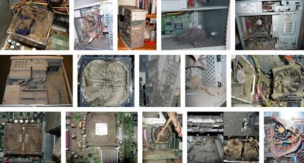
I deduced this from working on computers from before MSDOS and ripping more than a few fans apart to lubricate their bearings to prolong the life a bit (until I could get a new fan). {as I keep saying, I'm one of those people who open up sub-assemblies that were never intended to be opened.*}
Back in the days of CP/M fans were six inches square, made out of die-cast ali, and were simple "impedance protected" induction motors powered by the mains.
These were displaced by low voltage fans, typically 12 volt, and right from the outset these were electronically commutated (and often proudly marked as such). Never once have I seen a muffin fan with a brushed DC motor (the only kind that behaves anything like a resistor) and there are a couple of good reasons for this; first is operating lifetime - the brushes would wear out long before the bearings, and that is quite soon enough (just having replaced the squealing fan on my video card).
{in fact since I mostly work on older computers these days replacing distressed fans is something like half of all repairs, certainly a major proportion.}
The second is that some sparking and therefore electronic hash is generated by the brush/commutator interaction and this is the last thing you need inside your computer. The electronic noise generated by electronic commutation is predictable and tractable, the fan manufacturer can easily kill it at source (at least more easily than brush hash) so it's no problem for the PSU manufacturer or computer assembler.
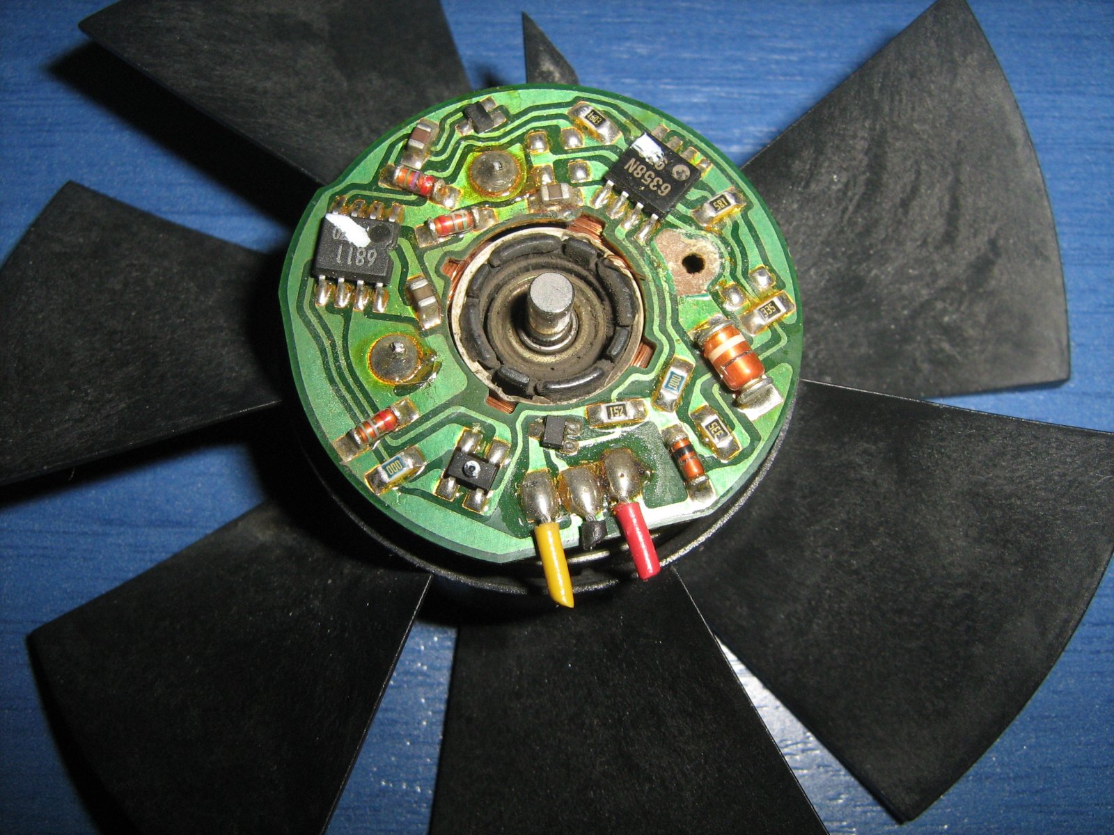
Early versions used a fairly simple circuit with a Hall Effect magnetic sensor returning the position of the rotor (the outer ring is actually magnetised into a number of poles).
Later versions seem to have lost the Hall sensor in favor of the cunning trick of using the inactive drive coil(s) as the rotation sensor. These are tiny PCB's we don't give much thought to, but they are quite a bag of tricks these days, and all that extra silicon complexity must still be worth it over brushes and a mechanical commutator from the fan manufacturers PoV.
Surprise! :crazy2:
Quote from: EnzoPop a dead one open sometime and explore.
And the interweb being what it is, somebody has already done it for us.
I see a bridge rectifier (4 legs), 5 diodes (orange glass), a couple of transistors (3 legs) and a couple of IC's de mystery, 8 legs each which could be anything from a simple sub-systems to a full-on microcontroller...or two;

{* SWMBO's car (Subaru Liberty) developed a nasty little pause. Several mechanics tore their hair out over it for weeks, computer? ($800), sundry sensors? ($80 a pop). But they wisely held off because nobody could be sure. Then my son (the supervising mechanic) took it for a blast and pointed to the air intake sensor. "The salmon mousse" he said. Cleaning the plug and socket seemed to cure it for a while, but it would creep back over time and SWMBO got so frustrated she was talking about selling the best handling car I've ever driven (all-wheel drive tracks like F-1, astonishing on highway or dirt).
Finally I ripped the sensor assembly off and opened it up for a look-see, and presto, right behind the socket was a row of solder joints, and one was obviously broken and just touching. A dab with a hot iron and the case was closed. Totally cured. Finito.}
#99
Tubes and Hybrids / Re: Peavey Classic 30 Output Tube Filament Wiring
April 22, 2015, 01:36:20 PM
#100
Amplifier Discussion / Re: Output impedance of tl072 input buffer
April 22, 2015, 01:25:03 PM
To a first approximation it's zero.
It's actually about 200 ohms, but it's so low compared to the values in your tonestack as to make no never mind.
On the datasheet the equiv cct shows two 64 ohm emitter resistors into a 128 ohm series resistor to the output, so it's at least 128 and more like 200-odd.
In LTSpice you are going to use an op-amp model, and this will have the internal source resistance accounted for. You can find a TL07x model at Yahoo LTSpice group, a great resource.
Or you could measure it. 8|
An op-amp provides almost perfect voltage source drive from very low impedance which is just what this tonestack wants. It's the load on the tonestack output that is quite important, generally the higher impedance the better.
#101
Amplifier Discussion / Re: Transformer Tricks
April 22, 2015, 01:04:57 PM
Well, leaving aside the 39kHz power oscillator, when you want lots of horsepower these things get big. And heavy. Great blocks of steel and lashings of copper. Not really ideal for aircraft. 8|

(big 3-phase transmission tranny under repair)

(moving decommissioned power station transformer)
I think the ferrite ring amp looks like fun - a MagAmp Cricket.
(big 3-phase transmission tranny under repair)
(moving decommissioned power station transformer)
I think the ferrite ring amp looks like fun - a MagAmp Cricket.
#102
Amplifier Discussion / Re: Thermostat/Fan
April 22, 2015, 12:32:05 PM
I was actually pretty dubious about the 90/10% thing at first, but it seems to have checked out over the years. The 90/10 may be a bit extreme but there is still very wide scope for quieting down noisy equipment fans.
:lmao:
With a DMM on Ohms range?
The short answer here is that the computer in the fan thinks it is being powered by a very flat battery (and I'm only surprised that the reading wasn't all over the place).
The key thing here is to understand that the fan contains a tiny computer, a very simple one, but that still needs a certain amount of voltage to bootup and operate correctly, then the motor coil drivers are activated.
It is because this fan is so UN-resistor like that we resort to measuring its current indirectly as the drop across the series resistor. These fans are emphatically not a resistor and behave nothing like one, they do not obey Ohms Law because they are dynamically doing stuff inside, switching motor coils on and off.
A DMM measures resistance by applying a constant current and reading the resulting voltage directly as resistance. This means the probe voltage is highly sensitive to loading, only microamps available.
Quote from: HawkVoltage across fan--4.11V
:lmao:
Quote from: HawkI tried measuring the fan resistance but I'm getting a really large number--177k--so I must be doing something wrong.
With a DMM on Ohms range?
The short answer here is that the computer in the fan thinks it is being powered by a very flat battery (and I'm only surprised that the reading wasn't all over the place).
The key thing here is to understand that the fan contains a tiny computer, a very simple one, but that still needs a certain amount of voltage to bootup and operate correctly, then the motor coil drivers are activated.
It is because this fan is so UN-resistor like that we resort to measuring its current indirectly as the drop across the series resistor. These fans are emphatically not a resistor and behave nothing like one, they do not obey Ohms Law because they are dynamically doing stuff inside, switching motor coils on and off.
A DMM measures resistance by applying a constant current and reading the resulting voltage directly as resistance. This means the probe voltage is highly sensitive to loading, only microamps available.
#103
Tubes and Hybrids / Re: Peavey Classic 30 Output Tube Filament Wiring
April 22, 2015, 12:11:02 PM
Well I keep saying that our assumptions are what bring us unstuck - I made an assumption and promptly came unstuck.
We need to be clear here about the difference between the heater voltage and the heater-to-cathode withstand voltage, Vh-k(max).
I've encountered valve heaters that range from 1.2V right up to 115V and lots of different voltages in between depending on the intended duty (but never a 240V one 8|), but by far the most common are 6.3VAC.
This is just the heater voltage, the bit that lights it up, and is pretty similar to a light globe, only duller. As a Rule of Thumb for the valves we encounter with thoriated tungsten cathodes this should be within +/-5% of the manufacturers specification - at the socket.

The heater is within a long thin cylinder that is the cathode and is insulated from the cathode with what looks like a ceramic material. Like all insulation this has an upper voltage limit and that is what the Vh-k(max) rating is, the maximum heater-to-cathode voltage allowed. Typically 100-200V this also can vary over a wide range depending on the intended service of the valve.
With the types of valves we commonly encounter in guitar amp circuits the heater-cathode voltage rating is hardly ever an issue, but the split-load phase inverter is a common situation where it might come a bit close.
This stage idles with about two-thirds of the supply on the anode and about one-third on the cathode. Assuming a 300V supply that will be Va=200V and Vk=100V.
On positive signal swings the valve will turn on and at full drive the anode and cathode voltages won't be much different, somewhere around half the supply or 150V, and that's not far off the maximum 180Vh-k rating for 12AX7's and the like (keeping in mind the actual heater power is normally at ground potential). The implication is that for that valve the supply shouldn't be higher than400V 360V.
The cathode follower, say used to drive a tonestack or as a Line Out or Fx Send buffer is another case where we need to take care because it may be possible for the cathode to go almost to the supply voltage on positive signal peaks.
Note that these are design considerations, say if you are building your own amp, but heater-cathode failure is quite rare in general amp servicing.
(ed to correct voltage)
Quote from: Hawkhad it in my head that tube heaters were only capable of handling a small voltage but not a large one--I checked a 12AX7 data sheet and it showed max rating Vh-k 180volts.
We need to be clear here about the difference between the heater voltage and the heater-to-cathode withstand voltage, Vh-k(max).
I've encountered valve heaters that range from 1.2V right up to 115V and lots of different voltages in between depending on the intended duty (but never a 240V one 8|), but by far the most common are 6.3VAC.
This is just the heater voltage, the bit that lights it up, and is pretty similar to a light globe, only duller. As a Rule of Thumb for the valves we encounter with thoriated tungsten cathodes this should be within +/-5% of the manufacturers specification - at the socket.
The heater is within a long thin cylinder that is the cathode and is insulated from the cathode with what looks like a ceramic material. Like all insulation this has an upper voltage limit and that is what the Vh-k(max) rating is, the maximum heater-to-cathode voltage allowed. Typically 100-200V this also can vary over a wide range depending on the intended service of the valve.
With the types of valves we commonly encounter in guitar amp circuits the heater-cathode voltage rating is hardly ever an issue, but the split-load phase inverter is a common situation where it might come a bit close.
This stage idles with about two-thirds of the supply on the anode and about one-third on the cathode. Assuming a 300V supply that will be Va=200V and Vk=100V.
On positive signal swings the valve will turn on and at full drive the anode and cathode voltages won't be much different, somewhere around half the supply or 150V, and that's not far off the maximum 180Vh-k rating for 12AX7's and the like (keeping in mind the actual heater power is normally at ground potential). The implication is that for that valve the supply shouldn't be higher than
The cathode follower, say used to drive a tonestack or as a Line Out or Fx Send buffer is another case where we need to take care because it may be possible for the cathode to go almost to the supply voltage on positive signal peaks.
Note that these are design considerations, say if you are building your own amp, but heater-cathode failure is quite rare in general amp servicing.
(ed to correct voltage)
#104
Tubes and Hybrids / Re: Peavey Classic 30 Output Tube Filament Wiring
April 21, 2015, 04:17:10 PM
Now we have the actual circuit, I stand corrected. This particular amp uses a singular 36VDC heater circuit.
My remarks above relate only to the almost universal use of 6.3 or 12.6VAC heater circuits in valve guitar amps.
My remarks above relate only to the almost universal use of 6.3 or 12.6VAC heater circuits in valve guitar amps.
#105
Amplifier Discussion / Re: Thermostat/Fan
April 21, 2015, 04:01:49 PMQuote from: J M FaheyIt runs slower than usual, but moves air around and makes very very little noise.
A friend worked at (then) Telecom Australia Research Labs and told me that the noise from fans in the new AXE's (computer exchanges) going in had become a problem, so they did a little project which came up with the astonishing discovery that "90% of the cooling effect comes in the first 10% of the rev range". Since these were 240V fans the simple fix was to reconnect them is series pairs running about half speed.
Since then I've quietened down a number of older computer systems using capacitive droppers in series with the (mains) fans and can confirm half speed makes next to no difference to the internal temperatures.
A properly sized heatsink really only needs the assistance of a gentle breeze to push away the hot boundary layer of air clinging right against the fins, and almost full performance is restored. All a full-speed all the time howling gale does is introduce more fluff faster.