Menu

Show posts

This section allows you to view all posts made by this member. Note that you can only see posts made in areas you currently have access to.

Show posts Menu

Messages - Roly

#136
Tubes and Hybrids / Re: Rebuilding Marshal Amp
April 02, 2015, 07:22:53 PM
{Now that's what I call a stack - dig all that cone area  :lmao: }


JMF provides some excellent advice.   :dbtu:

Assuming that the Alembic is running on a supply of around 250 volts you have a very classic preamp designed by Leo Fender (who had just the odd clue or two), a very well worn path for very good reason - it works well with guitar and has been a proven winner for over 50 years.  You will note that this circuit comes via R.G.Keen's site, another gentleman with the odd clue.   8|

{mind you, in my opinion most of the classic sound of a valve guitar amp comes from a valve output stage driving an output transformer, but that's a whole other discussion}


Quote from: CraftyZAif I increase the gain on the left I can create a stronger distortion

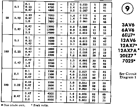
How?  A triode is not an op-amp with a huge hidden reserve of gain available for the tweeking of a resistor value.  The first stage is already operating at or close to flat tack (see the "V.G.", Voltage Gain, column in the RCA table above) and you are already trying to thread your guitar signal through the eye of a headroom needle.  Increasing the gain would only make things worse.

Why?  Your question suggests that you have missed the point of the second part of my post above.

The characteristic "tonality" of a triode (or JFET) comes from using it in its linear range between cutoff and saturation.  If you don't want the characteristic tonality or voicing of the valve and only want square waves then you can simply use a 50-cent op-amp and diode clipper and save yourself an awful lot of bother; the fact that it's a valve just becomes purely decorative.

A problem with the low supply voltage is that the linear operating window is seriously restricted and the gain stage prone to very easy, far too easy, overload (clipping).  Using a higher supply means that the triodes have a larger linear operating range where you will get the classic characteristic preamp distortion - "clean" but harmonically rich.

What you are suggesting would result in wall-to-wall clipping under just about all playing conditions and makes the choice of the gain device quite immaterial.

Do you want an amp that has some character, a range of voicing, or do you just want a grunge engine?

Perhaps you should build what JMF rightly calls "a toy, just a classroom demo" so that you can experience what we are trying to explain. 
#137
Owls, even big ones, like to stay off the radar which is why the one on the Canberra park, particularly being active during daylight, is such a curiosity it is bringing birdwatchers from all over.

We also have a much smaller fella called a Tawny Frogmouth which is seen more often because it's a late afternoon/early evening hunter and it hangs out in the lower branches pretending it's a branch.  It's possible to get within arm's length for a really good look while it repeats to itself "I'm a branch ... you can't see me ... I'm a branch".


Like I giveadamn?

Spot the bird.

Owls generally like to sit on a roadside marking post on a bend above a straight so they have a clear view of anything crossing the road and can just glide silently down ... and wallop!  Dinner.

One time I was doing a farm mind, driving out each evening, and night after night for about two weeks I'd come around this corner and there would be a Powerful Owl sitting on a side marker post (and taller than, ~4ft head to tip), and some nights it would take off and fly just above the front of my car in the spill of the headlights giving me a great view, and the wingspan was significantly wider than my car (Toyota Corolla).  Bloody awesome!

If you live in the Bush, or more specifically the forest, you have daily critter encounters.
#138
Amplifier Discussion / Re: Ampeg VH 140c....
March 31, 2015, 08:05:50 PM
Can't help you with setup specifically but a Google image search on "ampeg VH140c" turned up hits for schematics and PCB overlays at;

http://elektrotanya.com  (one of our favorites), and may also have a users manual, and;

http://javajunkiemusic.com/Audio/misc  (pages 1 to 9)

HTH
#139
The Newcomer's Forum / Re: newie here...
March 31, 2015, 08:02:17 PM
Hi jay4cars, welcome.


We all need some help sometime (particularly when the magic smoke gets out), and that's what this forum is about.
#140
Oh yeah, great place, great wildlife, great climate ... shame about the people.   xP

Much happier where I am now.   :dbtu:
#141
Tubes and Hybrids / Re: Rebuilding Marshal Amp
March 31, 2015, 10:18:29 AM
Year, sure, they will still work down to stupid voltages, but you did ask what it would sound like, and from a techo-guitarist point-of-view, better on higher supply voltages.  I'd guess the people at RCA (12AX7) and Mullard (ECC83) would raise an eyebrow at supply voltages less than 90.  "But why" I can hear them asking, "when it is easy to run them at their design voltages?"

Quote from: CraftyZAI've got 2 x 12x7 tubes (not matched)

There is no point at all in paying for matched preamp valves, they aren't operating in push-pull like an output stage.  Matching output valves is a Hi-Fi imperative and implies a reasonable quality output transformer, but again some mismatch in the output valves and a mid-fi output transformer gives rise to distortions that guitarists like.  One tech here goes as far as saying that "what you do for Hi-Fi, try doing the opposite for guitar" - a bit extreme perhaps, but guitar amps ain't Hi-Fi amps and we need to constantly question the "truths" that sneak in from the Hi-Fi world because they often don't apply.

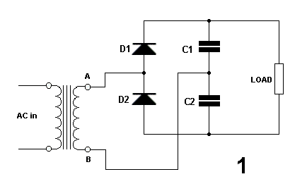
Given the very low current draw of preamp stages a voltage multiplier such as a doubler;


... tripler;


... or quadrupler;


... is quite practical.
#142
Tubes and Hybrids / Re: Rebuilding Marshal Amp
March 31, 2015, 08:51:54 AM
Quote from: CraftyZAthen some resistors blew up, and some tracks melted.

It would seem that you need to read this thread;
http://www.ssguitar.com/index.php?topic=2093.0

A limiting lamp really is an essential tool when working on solid-state amplifiers.


On the input socket pins 4 and 5 should be connected together to silence the amp when nothing is plugged in.


Quote from: CraftyZAknow what it will sound like?

Running on only 60 volts it will have little or no headroom to clipping. 

There are good reasons why the lowest supply voltage RCA characterised the 12AX7 for was 90 volts, and why all of the classic era valve guitar amps invariably used around 200-300 volt supply.

There are two basic requirements when setting the idle or DC conditions of a triode stage (selecting the anode and cathode resistor values);

- the anode voltage should idle about half the supply,

- the cathode voltage should be higher than the largest expected signal peak.

As the supply voltage is lowered it becomes harder to satisfy both of these requirements, and in fact the anode voltage in the Instructables design will idle around 50 volts meaning an output headroom of only 10 volts to clipping.

We normally assume that a guitar has an output of around 500mV average with peaks to 1 volt.

In the classic application the cathode voltage is between one and two volts, so it is quite hard to clip the first stage even if you belt the guitar.

On a 60V supply the cathode voltage drops to around 450mV so even average playing is getting you into clip territory.


from RCA databook

One of the things about these triodes that guitarists like is the fact that they are not actually linear, that positive signal excursions tend to get stretched while negative excursions tend to get compressed, in other words they produce some harmonic distortion.  The larger the signal swing on the grid the more this occurs, conversely with a limited grid swing there is less of this effect, and a low supply voltage seriously limits the available swing until clipping occurs.

This classic load line from valvewizard illustrates the point;

Vsupply = 320 volts

The distance along the blue 100k load line between Vg=0 and Vg=-0.5 is much greater than the distance between Vg=-2.5 and Vg=-3.  The spacing between intersections gets continuously shorter between Vg=0 and Vg=-4, so as the signal level goes up so does the harmonic distortion.  In a preamp this is what "tube tone" is all about.

If we move the 100k load line to the left so it runs from 60 volts to 0.6mA we can see that there is much less swing available to clipping, but also that this compression effect is less, so we will get less harmonic distortion before the onset of clipping, less "tube tone", then grunge.

I understand that people are afraid of high voltages, but running a preamp on voltages less than about 90 is a bit like running your car on kerosine because you are afraid of petrol.

Getting a 200-300V supply at a couple of milliamps is trivial, certainly more trivial than that switch mode converter, and a couple of small back-to-back transformers don't have to be sealed up in a metal box and carefully filtered lest (albeit supersonic) switch mode artifacts turn up in your signal chain.

{BTW the 100k anode load resistors R1 and R2 don't need to be 1 watt, half watt is sufficient even on a 300 volt supply}

HTH
#143
Tubes and Hybrids / Re: Rebuilding Marshal Amp
March 30, 2015, 03:04:48 PM
Hi CraftyZA, welcome.


Quote from: CraftyZAI'm rebuilding a marshal valvestate S80 amp.

Why?
#144
In the Si version there are three resistors in the bias divider, "?" pot, the effect pot, and 100r.  The effects pot changes where the AC signal is injected into the DC bias chain but it doesn't change the DC conditions on the Base of the second transistor.

In the Ge version the 820k ("?") goes to the effect pot wiper instead of the top of the pot, so that when the effect pot is changed it also changes the total value of the bias divider chain, and thus the voltage at the Base of the second transistor.

If you are having trouble visualising it try considering the two limiting cases, effects pot at max, and at min.

At max the divider chain consists of 820k, (Base) 10k effect pot, 100r.

R = 820k + 10k + 100r = 830.1k

I = E/R
9/0.8301 = 10.8421uA  (volts, megohms, microamps)

VB = I * R
10.8421 * 10.1 = 109.5052mV

At min it consists only of 820k and 100r, with the Base connected via the 10k pot (which will have very little effect because of the low Base current).

R = 820k + 100r = 820.1k (10k less than above)

9/0.8201 = 10.9743uA

10.9743 * 0.1 = 1.0974mV

At this setting the transistor will be cut off due to insufficient VB and only conduct on signal peaks.

This also means that the driving stage will now be seeing a load of only 100r and its gain will therefore be seriously reduced (true for both versions).

In simple terms the effect pot in the Si version changes the AC level but not the DC level at the Base.  In the Ge version both the AC and DC levels change.

HTH
#145
Silicon version internal;

Shame on WEM for not putting in one more resistor to protect the second transistor from twiddling guitarists.  If the required value is 120k then use a fixed resistor rather than a (circuit-destruct) trim pot.  Murphy's Law dictates that if it is possible to crank it around and smoke the transistor, someone, sometime, will do so (most likely you in a moment of forgetfulness).  If you must use a trimpot then at least put a 47k in series with it to cheat Murphy.

This is the germanium version;


The "effect" control has a different action here to the later silicon version in that it changes the bias on the second transistor.  Pity they didn't call it something else because it's significantly different.
#146
Quote from: VintageSilvertoneI still think it would be safe to replace the 9158s with a pair of MJ15015s, as they are not germanium.

Perhaps, but only if they have failed.  Otherwise leave well enough alone.


Quote from: VintageSilvertoneI noticed was a fairly prominent hum when the volumes were all the way off

Ah.  Now you have a symptom that does point to the power supply electros and is not surprising in a vintage amp.

On the bench I'd pull out a couple of chunky electros and tack them across the existing ones just to prove the point - there should be a notable improvement.  Or you could just replace them on spec, they aren't terribly expensive, and it's certainly not a bad idea given the age of the originals.
#147
{oops.   :-[ }

Quote from: phatt on March 27, 2015, 04:25:17 AM
But what is wrong with the amplifier? Headscratch??
Phil.

Quote from: VintageSilvertone on March 27, 2015, 11:31:36 AM
As long as I had it apart, I thought I might replace pluggable parts such as the transistors and the large capacitors.

Nooooo.  If it ain't busted, don't fix it!  It is easily possible to do more harm than good (e.g. fitting Si NPN transistors to a working Ge PNP amp   :-[ , making it "not working", and maybe terminally damaging it in the process).

If any amp has been in storage for a long time then there is very good reasons to be suspicious of the power supply electrolytics, and bring it up initially on a Limiting Lamp, then replace them if they shows signs of being faulty - and that goes for all components.  If they look okay and test okay then leave them alone.  (one exception to this is waxed paper caps in very old valve gear, but that's another story)

There are an awful lot of guitar amps that don't make the watts claimed, and frankly screwing 100WRMS out of a pair of old Germaniums seems like a bit of an ask to me.  You certainly wouldn't get it from a pair of 2N3055's in a similar circuit; in practical terms they run out about the 50 watt/8 ohm level (and don't like 4 ohms much).


#148
Amplifier Discussion / Re: Marshall Valvestate 8100
March 27, 2015, 04:09:34 PM
I actually meant just changing the collector load from a 1k to a 10k, not stepping through "1k to 10k", however by going through it in steps of 1k the picture should be all the clearer. 


Quote from: HawkI'm assuming we're using variables to understand the workings of a transistor

Quite so.  Remember that the bias is to set the device idle condition, and in use it will be receiving an input signal that is superimposed on the bias, so while the resting Collector voltage will be half the supply (roughly), when driven with an actual signal the Collector voltage will swing up and down in sympathy.

{half the problem with bias networks is getting the bias in there without stuffing up the desired operation too much.  Early transistor guitar amps often had a real problem maintaining a reasonable input impedance for guitar (1M min) due to the effects of the required bias networks, and I've seen some as low as 47k.}


Quote from: Hawk
here's my story:
...
I'm having a blast and loving it!

Well I wish you the very best of it.   :dbtu:   May your days be filled with interesting faults.   ;)

I survived a 240VAC belt as a breedling by sticking my fingers in a live light socket, and it seems to have set down a path of curiosity that lasted a whole career and into retirement.  Some people do crosswords, some climb mountains, but I get my rush from designing, building, and repairing electronic/electrical stuff.

We have a community-run "Infolink" in town which provides walk-in Internet access, and occasionally one of the punters will do "something" to one of the machines that needs to be sorted out.  Mostly the resident SysOp is on top of things, but a couple of months ago he mentioned that one of the machines had "forgotten" it had a CD drive.  He had tried all the obvious things like replacing the drive but to no avail, and asked me if I'd take a look.  After a lot of stuffing around covering the obvious, then a fair bit of Google research, I found mention of a possible problem with the registry entries, so taking the bit between my teeth (and my heart in my hands) I got stuck into editing the Registry, and presto, the drive was back.  Yo!

Particularly with obscure faults, or "stinkers" that have been hanging around for some time, there is a real sense of having won one over entropy (and a certain amount of dancing around and air punching).  YES!  Humans - 1, contraption - nil.  "Take that!  Who's King of the @$^&ing castle then?"  It's a great feeling.


Quote from: HawkRoly thanks for taking the time, I feel like a real taker on this forum and hope that one day I can give back. :cheesy:

My pleasure.  I also get a charge out of teaching (electronics, physics, some maths), particularly when it falls on fertile ground (and your trainees are coming back from Tech waving "Distinction" results).  My tutors and mentors struggled to teach me, and now it's my turn to give back (forward).


Quote from: Hawkshould I be thinking about getting a DC Power Supply?

Build your own test gear.   :dbtu:
#149
{I'm just too trusting, right?}

Quote from: J M FaheyFrom the mind of the "designer":

Quote
b) guitars have 500k volume pots
c) if amps and guitars have 500k volume pots, then all volume pots must be 500k

Now there is a real gem of design drivel.  ::)   The "designer" seems so oblivious to the fact that this is total rubbish that they are willing to post it on the net.


Quote from: J M FaheyThen, why didn't they use the proper 50k pots?

My own thoughts exactly.


Quote from: J M Fahey4) not forgetting that it's probably wrong.
Very much doubt it's the actual circuit found inside an original PepBox

And you're right.  Looking at pix of the actual PepBox circuit board I notice that the output 56k is in the original, however there are also some resistors with values not on the circuit above, 470k, 1k5, 820k, and what looks like 18k, so the circuit above is at least a pretty poor match to the original.  When four out of seven resistors are different values and both transistors have been changed from germanium (ACY11's) to silicone (BC107's) you have to wonder if this highly modified circuit deserves to be called a "PepBox" at all.  I certainly don't think so, even "derived from" would be a stretch.  Avoid.


When you are looking at circuits, particularly on the net, and find something like the "?" control that will blow up the associated transistor if turned too far, loud alarm bells should be ringing.  This circuit follows the "you never find just one roach in a kitchen" rule, even in a simple circuit like this one, and you should be very alert for other electronic bloopers.
#150
Hi VintageSilvertone, welcome.


Output power:

+/-35V rails, 5.33 ohms load

35/1.414 = 24.75VRMS

P = E2/R

(24.75^2) / 5.33 = 114.93watts RMS.

So yeah, "150" is peak power, it's a 100 watt amp.


All these devices have to do is meet or exceed the specs of the transistor they are replacing; maximum voltage (35*2=70), maximum current (35/5.33=6.57amps) and maximum power (about the same as the output power, split between two devices, 115/2=57.5watts).

As for the driver, as long as it will physically fit I'd try another MJ15015 (which is generally slightly superior to the 2N3055).

MJ15015
IC(A) = 15, VCBO(V) = 100, VCEO(V) = 60, PD(W) = 115, Package = TO-3, HFE(Min/Max) = 20/70


HTH


ed to correct