Menu

Show posts

This section allows you to view all posts made by this member. Note that you can only see posts made in areas you currently have access to.

Show posts Menu

Messages - Roly

#106
Amplifier Discussion / Re: acoustic 150 zobel?
April 21, 2015, 03:38:18 PM
Square wave test - caution: (I should have said) if fed through the preamp the EQ will have a profound effect on waveshape, therefore this test is really only meaningful when applied to the power amp alone (e.g. via Fx Return).


Quote from: J M Fahey* wobbly and double-vision sinewave?: the sinewave is perfect, you are having a sync problem in your scope.

My first thought also.
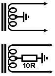
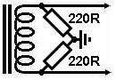
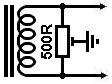

Your enemy;


The lower trace is showing bursts of high frequency parasitic oscillation on a signal. Unlike straight supersonic oscillation parasitic oscillations only occur under certain circuit conditions of drive and load, the circuit is said to be only conditionally stable, and this is the implication of the Acoustic caution mentioned by gbono above.  Ideally all amplifiers should be UN-conditionally stable under all load and signal conditions.

Using a square rather than sine wave is poking a stick down its hole, a serious provocation for an instability to show itself.  The sharp edge of the square wave is an electronic version of giving it a whack on the case.  If anything is going to ping, ring, or burst into HF oscillation, that's when it is going to be "shocked" into doing it.

I've encountered the very occasional roasted Zobel, but apart from obvious stuff like the cap shorted, it's hard to tell what conditions may have caused the failure since they always seem to be situational, unreported to me (e.g. using a curly cord for the speaker), and no other fault can later be found in the amp.  I've had amps in for other repairs where the Zobel must have been burned out years before (e.g. fluff accumulating on the burnt resistor), the cause lost in the mists of time, and perhaps multiple ownership.

Most times a bit of detective work will develop a reasonable explanation for a fault, (e.g. one of the speaker leads has an intermittent short), but there are also a small percentage of repairs where is is not obvious from the equipment and there is a lack of other information.

{I'm reminded of a multi-headphone amp from a studio with one output seriously fried.  The only thing I could say for sure is that there wasn't enough power available within the unit to cause that much damage, so the power had apparently come in via the headphone socket.  I can only guess that somebody accidentally plugged an amp speaker lead into the headphone output (both 6.5mm) and gave their amp a thrash.  It certainly isn't the first time I've seen damage from that mistake.  For a conscientious repairer a guess, even a good one, isn't very satisfactory because it's nice to be certain, but without somebody putting their hand up it had to remain a mystery.}


#107
Quote from: Matecif a valve fails, all other will turn off too.

Hi Matec, welcome; but that needs a little qualification.

In old b/w ac/dc TV's the entire heater chain was in series so all those valves could be heated directly by mains voltage, and if one failed they would all go out (like xmas tree lights).

In the typical guitar amp situation however the 12.6V is applied to each twin triode and to the two output valves in series (they are not "independent").  If one of these heaters fails then its companion goes out, but not all the heaters - they are series pairs in a parallel string.  In a 12A?7 this means that one heater failing will make both in that tube go out, and that if one output valve heater fails they will both go out.  All other intact series strings will remain alight.


Quote from: HawkSo when an EL84 <filament> fails is it possible that it's filament will still be intact and feed voltage to the other series connected output tubes?  :-\

No.  Valve heaters are like light globes, they are either intact and passing current, or they are open circuit with no current flowing, and terminally stuffed.  You will get the entire heater supply across the open heater, and nothing across the good one (because no current is flowing, the failed valve has effectively switched the good one off).

One basic reason for using a 12.6V heater circuit rather than the more traditional 6.3V circuit is that the transformer required is marginally less expensive (current capacity pushes up transformer cost slightly faster than voltage).  To the owner builder this is of no matter, but when belting out hundreds or thousands of a design the bean counters get to have the final say over engineers.

At first glance there may not seem a lot to choose between running a heater circuit at 6.3 or 12.6 volts, but from a design PoV there is quite a big difference.  It has been traditional valve amp practice to run the heaters on 6.3V and to ground the center point of the heater winding, meaning that it's actually two 3.15V circuits in anti-phase.


Inside the almost universal twin-triode used in the preamp stages this means that there is a virtual earth point in the middle of each section cathode, and therefore the AC voltage applied to the heater, being anti-phase, cancels out capacitive coupling of heater mains hum to the cathode.


Apart from using a center-tapped heater winding the same effect can be obtained using a phantom mid point created by grounding the mid point of two 100 ohm resistors in series across the heater supply.  In fact in high quality valve amps this is often a 100 ohm pot with a grounded wiper across the heater supply, known as a "hum dinger", which is adjusted for minimum hum output, best AC balance to ground.


12.6V heaters give up this possible benefit because the phantom mid-point, the virtual earth, now occurs between the two heaters, not in the middle of their cathodes, so hum balancing is impossible.

When building, the commonly available transformers with a 6.3v 2Amp winding are often larger and somewhat more expensive than 12.6V 1Amp trannies, however the lack of high voltage trannies these days mean that many owner-builders use a pair of transformers back-to-back, and one of the more common and therefore fairly cheap options are transformers designed for QI downlights, mains voltage to 12.6V at an amp or several, and given that this arrangement normally has spare 12.6V current capacity it makes sense to use this intermediate voltage for the heaters.


I want to introduce you to a dead German bloke, Kirchhoff (1824 – 1887, who came along not long after Ohm, and built on his Law).


Gustav Kirchhoff

Kirchhoff formulated two Laws that carry his name; Kirchhoff's Current Law (KCL) and Kirchhoff's Voltage Law (KVL).  Now while these look a bit complex they are really very basic in concept, almost "obvious" - electricity does not accumulate anywhere in a (resistive) circuit.

Quote from: KCLThe principle of conservation of electric charge implies that:

    At any node (junction) in an electrical circuit, the sum of currents flowing into that node is equal to the sum of currents flowing out of that node

or equivalently

    The algebraic sum of currents in a network of conductors meeting at a point is zero.


If that were not the case we would be getting excess electrons in some places and a shortage in others, but that doesn't happen because what flows in also flows out.

From this we also get that in a simple circuit loop, such as output valve heaters in series, the current is the same everywhere in the loop.


Similarly;

Quote from: KVLThe directed sum of the electrical potential differences (voltage) around any closed network is zero, or:

    More simply, the sum of the emfs in any closed loop is equivalent to the sum of the potential drops in that loop, or:

        The algebraic sum of the products of the resistances of the conductors and the currents in them in a closed loop is equal to the total emf available in that loop.

http://en.wikipedia.org/wiki/File:Kirchhoff_voltage_law.svg

The sum of the voltage drops around your circuit is equal to the supply voltage.  Again, if it wasn't then electrons would be in excess or shortage somewhere.

The normal student reaction at first is "gee, that's heavy", followed a few minutes later by "what?  That's so obvious why does it need a Law?"  Maybe, but an intimate working understanding of both KVL and KCL are essential to effective faultfinding.

#108
Amplifier Discussion / Re: Thermostat/Fan
April 20, 2015, 12:52:35 PM
Quote from: Hawkyour post pointed me in many directions so I've been reading all about Bang-bang controller, hysteresis, control theory, Schmitt Trigger, and Driver LM3914.
:cheesy:


That's great.  I try to set search leaders in italics, "if it takes your interest, Google/Wiki this".

Control Theory is all around us every day.  There's a modern glass lift in a nearby shopping centre that not only has all the workings visible, it's a wonder of Control theory they way it arrests with almost no obvious G-change, to exactly level.


The only fan that is speed proportional to voltage is one with a DC motor (e.g. car heater/AC fan, Thermatic cooling fans, most car motors in fact).

These "computer" or Muffin fans are a very different animal.  The power goes into a small circuit board containing lot of silicon.  It operates a bit like a stepper motor in that it has three phases driven by a controller on the board.  This controller either runs because it is getting enough voltage, my guess is that dropout is about 3V, or it's not.

When it's running we can presume that its output pulse rate is constant, trying to run the rotor at full speed.  The reason it runs slow on lower voltages is because less current can flow in the motor coils and is overcome by the air drag on the blades.

I've never tried it but I presume that once the motor is up to speed, say at 12 volts, the speed would remain fairly constant for increased voltages, until the smoke came out.  I think.

Even at 12V it is likely that the 150mA is average, and that there will be impulsing at the commutation frequency, whatever that is, so it's anything but a pure 80 ohm resistor.

I certainly treated it as one in my ThermoFan design, but that mainly means putting up with an initial starting friction that requires the amp to get fairly warm.  Once it's away, after that it's almost purely proportional over say a 10%-90% range.


When in doubt, measure it, so out with your multimeter and measure the fan current on various voltages.   :dbtu:
#109
Amplifier Discussion / Re: Transformer Tricks
April 18, 2015, 08:53:13 PM
Thanks for those teemuk, but I hope you will forgive me for being a tad under-whelmed.

The US Navy publication from 1951 has a long list of MagAmp applications, and in 1951, just when solid-state devices were being invented, the MagAmp looked like an attractive proposition compared with valves (tubes).

Within a couple of decades that hopeful list would be shredded by an even better device, and the MagAmp, like the valve, effectively became a historical oddity.  {too odd, it seems, for even the excited Golden Eared Hyper-Fi-ist community.}

The Germans also did a lot of development between the wars of cold-cathode "gas" valves which were capable of astonishing amplification factors, but like MagAmps these were also swept away by devices and techniques that didn't suffer from their inherent limitations.

MagAmps still do what they always did, but it's hard to think of any application these days were the sensible designer wouldn't walk right past obscure MagAmp technology to something a bit more commonplace that works better.  Newer Melbourne trams for example use SMPS for smooth traction and regenerative braking, something MagAmp's can't match.  Worse, the advent of SMPS has made the winding of iron core transformers of any sort, let alone complex ones, an endangered art.

The Navy document gives a good impression of where things stood in 1951, but also shows how rapidly and how much things have changed since.  The MagAmp flip-flop is particularly amusing when you consider that your computer now contains several million solid-state flip flops.

I love steam engines too, but yagotta be practical.

{And I still sometimes take out a USB Ramstick or mini-SD card and just look at it in wonder.  Gigabytes of non-volatile storage, when my first computer had 512 bytes of usable space and drew amps of current.  :o }
#110
Preamps and Effects / Re: The JFET Bender Preamp
April 17, 2015, 10:17:19 PM
Thank you for a full and illuminating report on your investigations.  This moves things forward.

:dbtu:
#111
Amplifier Discussion / Re: Transformer Tricks
April 17, 2015, 10:31:59 AM
Magnetic amplifiers pre-date valves.  I've seen reference to them being used in gun fire control on WW1 battleships.

They are simple, robust, and capable of quite high power.  They are also inherently heavy and waveform distorting - an ideal servo amp on a big ship, not such a great audio amp.

Saturable reactors still get used occasionally for high power AC control, but it's getting rarer.

The audio amp is a bit like Class-D.  The 35kHz is the carrier that switches the core from state to state, the audio applied on another winding biases this switching up or down resulting in 35kHz PWM output.

If you think these are fun then you should visit a surviving cousin, the ferro-resonant Constant Voltage transformer, still widely found.
#112
Amplifier Discussion / Re: acoustic 150 zobel?
April 16, 2015, 08:34:41 AM
Quote from: ilyaaam i {right} to say that R404 and C404 make a zobel network across the output?

what would cause R404 to blow? my guess: amp plugged in without a load puts the output wattage across the puny 1W R404 and blows it up -

but then isnt that resistor just asking to be destroyed? ive seen one in another acoustic 150 that was blown literally in half...

Yes that is the Zobel network.  Doug Self says it's for high and very high frequency stability (but I personally wonder if it's Elephant-Proof Paint, insurance against something that is very unlikely to happen in a guitar amp not driving piezo tweeters or a crossover?).

{
Quote from: phattIf I recall, some Acoustic rigs have Hi freq horns? If so,
What would happen if the main speaker became disconnected?

Good observation.  Most likely the load would then look fairly capacitive due to the LF blocking cap in series with the pressure driver.

Perhaps you have in mind the 271;


The 150 seems to have a choice of 2x12;


4x12;


or 6x12 cabs;

}


C404 going short (or full power supersonic signal from somewhere).


No.  This is a solid-state amp so it looks like a battery, a voltage source with a very low internal impedance.  Unlike an amp with an output transformer (e.g. valves) it makes very little difference if a load is connected or not.  The supply rails dictate the highest voltage you will get on the output, say around 35-45Vpk depending on the amp rated power and load impedance.  The output can even go squarewave but there is no way the voltage can go higher than the rails.


Exercise:
Taking the peak output voltage you can apply it to the Zobel at say 10kHz (a reasonable maximum for a stage amp), work out the reactance of the cap, Xc = 1/(2 Pi f C), and thus the highest current through the Zobel.  You can then work out the power due to the current in the resistor.

At 0.1uF and 22 ohms/1 watt this is a pretty typical Zobel, they don't change much, maybe 0.22uF, maybe 47 ohms, but that's about it. {and as JMF says about chipamps.}

I cheated and used LTSpice.  The current in the Zobel at 10kHz/35Vpk is a bit over 200mApk.

200/root(2) = Irms

200/1.414 = 141.4427157

P = I2R

(.141^2)*22 = 0.437W  Well under its 1 watt rating.

Even with a lot of higher harmonics it still wouldn't be too uncomfortable at full power ('tho the power transistors might be).


Now let us assume that the cap has shorted and we just have the 22 ohm across the output.

35Vpk = 35/1.414 = 24.75247525Vrms, call it 25V

{intuitively we should estimate that a 22 ohm resistor across 24 volts is less than an ohm per volt and so is going to pass more than an amp, and an amp in 22 ohms is 22 watts.}

P = E2/R

25^2 / 22 = 28.40909091 watts.  One watt resistor --> POOF!.


There are a couple of possible ways here; either your experience of these amps is a statistical outlier, or perhaps the manufacturer had a generic problem with these caps (miss-specified, faulty batch, whatever).  You could "HiRel" this by using a mains-rated "X" or "Y" series yellow block cap.  These are available in 0.1uF, 240VAC (630VDC test) rating, and are self-healing if they punch through due to a mains spike, just a small loss of capacitance and they don't catch fire or short.

{I might use a scrounged one in my own gear, but a new one in a client's amp.}

Perhaps this amp encountered a supersonic signal somewhere, or possibly these have a generic supersonic instability problem, possibly as the caps age.  You could try putting a low level squarewave through it and see what it comes out like.  If there is any stability weakness you will see it as overshoot on the edges and possibly ringing oscillations.


I also had cheesy FM radio breakthrough on a Tandy PA used at a Remembrance dawn service(!) due to speaker lead pickup and no Zobel or output inductor to stop the RF getting into the NFB loop.  0.5 ohm 5W/ww in series with the output resistor fixed.
#113
Amplifier Discussion / Re: Thermostat/Fan
April 16, 2015, 06:19:10 AM
Quote from: EnzoStop thinking of the transistors as putting a voltage on the other side of the motor.  Think of them as a switch that completes the circuit through the motor.

e.g. mentally replace Q101/2 with a switch or relay; that's all they are doing, on-off.

When off the circuit is open at the bottom, so you will measure the -18V supply in both ends of the resistor, both sides of the fan, and on the collectors of Q101 & 102.

When on 150mA will be flowing, the collectors of Q101 & 102 will be ground (close enough), you will have 12V across the fan, and the other 6 volts across the fan dropping resistor.

{I think that the way this is drawn doesn't help understanding.  The British convention is to stack supply rails according to their voltage, so from the diode the switching stages would be drawn below the ground line to give a physical representation to the voltages, the -18V supply as the most negative coming in from the bottom.  It may not be obvious but the op-amp is running from a dual supply, so when its output goes low it will go below ground to -Vsup and turn on the transistor "switch".}


You may already get this, but a bit more detail.

Open loop (i.e. without NFB) an op-amp has a gain of at least 100,000 times, meaning that it only takes 10 micro-volts of input to produce 1 volt of output, or only about 300uV to swing the output rail-to-rail - mighty sensitive.  So when it's near its switching point it is highly sensitive to electrical noise.

One of the functions of applying hysteresis via Q103 is to spread the "on" and "off" temperatures, say on at 50ºC and off again at 30ºC (or whatever).

But there is also a fair bit of electromagnetic crud floating about, hum from mains, radio stations and whatall that can easily amount to 300uV, so at threshold the op-amp would be trying to respond to all this other crud and waggle about, producing what is called "chatter", or in a proportional controller "hunting".

By shifting the reference voltage via Q103 the circuit will flip over the first time any signal takes it over the threshold, and it will stay there until the voltage (+noise) falls enough to take it over the new lower threshold, where the action will reverse - nice clean switching both ways.

See also: Schmitt trigger.


Quote from: Hawkthe fan is rated at 12V/ .15 A. The -ve is 18. Do we use ohm's law to calculate  the voltage drop across  R108 to see that we will get -12 ve to the other side of the resistor?

Yes.  (ref: Enzo's excellent reply)

Around 12V we can consider the fan to be a resistor of R = E/I ohms, 12/0.15 = 80 ohms.


{Long rambling aside:

but we need to remember that if it's one of the almost universal "brushless" type then it's actually a tiny switch-mode controller in the hub that tries to run the fan at a fixed speed over a wide range of voltages, and may not behave like a resistor at all by the time you get to say 6 or 18 volts.

Despite this and needing a bit of a thermal kick to get it spinning, once started my proportional controller is surprisingly linear across the temperature range.  This is mainly because at low voltages (and reduced drive current) there is a lot of magnetic "slip" where the controller spins the field faster than the fan rotor can follow, and it settles to some balance between reduced drive and blade air drag.

It's a bit "second order" but electronics don't like to be thermally cycled, best when warmed up to a steady state and remain at that temperature (maybe for many years in the case of big transmitters and telephone exchanges).  With that in mind a proportional controller is better than a bang-bang controller in that it tends to keep the internal operating temperature more stable within a smaller range.

This generally comes under the heading of Control Theory.  I'd encourage you to at least skim this article since all the s.s. power amps we deal with are subject to these laws.

This is one of the earliest feedback controllers;

...which came to be needed early in the Industrial Revolution when steam engines were needed to run at constant speed for mine pumps, textile mills, and later electric generators.

Control Theory allows us to have systems that approach the required value in the shortest possible time with minimal overshoot, and to remain in a predictable band in normal operation.

As we have just seen Space-X are still having troubles getting the loop dynamics right for their Falcon-9 soft landing, and gives some insight to how well the Luna landers did.  They apparently have the vertical dynamics right, but not the lateral dynamics, so it was still moving sideways when it touched down, and fell over.

Vid - almost, but not quite;
https://www.youtube.com/watch?feature=player_embedded&v=BhMSzC1crr0
You can see the side-to-side sway is not stabilised before touchdown.

Good tech article;
http://www.wired.com/2015/04/analysis-falcon-9-crash-landing/

The function of the sideways motion;

y(t) = (-35.8)*t + (148)
{...ahem...}
y(t) = (-35.8 )*t + (148)

...may look scary but it's just y = kx+c from High School.

"Distance y as a function of time t is -38.5 metres per second, plus 148 metres" (presumably distance from the bullseye).  I'm not the first to observe that it looks more like -3.85m/s and 14.8m off, and that may be a clue to the problem, a simple decimal point error, and it wouldn't be the first.

I'm not laughing.  Getting this pencil to stand on its end in three axes is a pretty neat trick, particularly if its Centre of Gravity is below half the height.}
#114
Amplifier Discussion / Re: Thermostat/Fan
April 15, 2015, 05:50:49 PM
Quote from: HawkHope this is okay to post as this is an audio amplifier rather than a guitar amplifier, but same concepts.

Speaking for myself, I'm up for anything electrical/electronic.  Staging can include lots of "other" stuff like lighting desks, smoke generators, wireless links, big screen computer-driven displays, &c, covering a wide range of electronics and other technologies.


The component RT101 is a thermistor with a fairly steep temperature/resistance characteristic (but without the specific part number I can't find a datasheet).  Thermistors come in a very wide range of physical shapes so it could look like almost anything.


When the output of op-amp U101B is +ve diode D102 will be back biased, so there will be no current injection into Q101 or Q102 and the fan will be off.

For the output of op-amp U101B to be +ve, high, then the non-inverting input "+" must be higher than the inverting input "-".

As Q103 is a PNP transistor when the op-amp output is high it will also be off.

RT101 is marked as having a nominal resistance of 330 ohms at 25ºC, and this must rise as it gets hotter.  This means it must be a Positive Temperature Coefficient, PTC rather than the more common NTC, type.

When it gets to the same value as R103 the voltage on both inputs will be equal (this is a bridge arrangement), but the thermistor pushing the "-" input just a little bit higher than the "+" input will cause the output to go negative.  (The op-amp has no negative feedback and is operating in switching mode)

When this happens D102 will be forward biased and Q101, 102, and the fan will turn on.

Q103 will also turn on and cause the voltage at the "+" input to be pulled down a bit.  This has the effect of latching the op-amp in the new state, and requires that the thermistor cools down a fair bit before the opposite switch-over occur and the fan turns off again.  This difference between switch-on and switch-off temperatures is called hysteresis.

This comes under the general heading of a bang-bang controller, all or nothing, in contrast to a proportional controller that varies the fan speed over a range according to the temperature, like this one.
#115
Amplifier Discussion / Re: Ampeg BT15
April 14, 2015, 12:03:35 PM
teemuk, JMF, et al, Any other thoughts on that diode?  I'm not sure I understand what they were thinking there. 
#116
Quote from: bluesgroovethe older cube amps


(Errata: the title and caption should read Cube-40.  Model: SCL-40 Serial: 742799)

The full story;
http://www.ozvalveamps.org/repairs/cube40.htm
#117
Thank you. 

I  <3) anything when it's working.   8|
#118
Amplifier Discussion / Re: Ampeg BT15
April 13, 2015, 10:48:17 PM
Quote from: gbonoand replaced the output transistors

Why?  Were they blown?


Quote from: gbonoAfter reflowing the solder joints I have noticed a pretty strong hum that wasn't presnt before  :grr

If it ain't busted, don't fix it.

This is a paradoxical problem with "routine" or "preventative" maintenance - there is always a finite chance you are going to introduce a new fault into a previously working assembly.  Three little O-rings (interestingly part of a safety monitoring system).

As well as "do no harm" we need to remember "if it's working, leave it alone".   8|


Quote from: gbonowhat is the function of the diode (D1 connected to Q10 emitter and 300 ohm power resistors

That is a bloody good question.   :dbtu:

{BTW Q10 is misdrawn, it should be a PNP with the Emitter up, pointing downward to the Base.  It looks like very primitive CAD so they may not have had a PNP symbol.}

What you've got is (roughly) arrangement A;


Points to note;

- the upper an lower cells are not voltage gain matched.  The upper cell is a Darlington or (super) emitter-follower with unity voltage gain, and the lower cell is a buffered grounded-emitter amplifier with voltage gain.

- The driver emitters are returned to the next stage 1 ohm "emitter" resistors to provide local DC and AC feedback.

(another local negative feedback resistor of about 47 ohms is sometimes inserted in the emitter of PNP driver Q3 to try to better balance the cell voltage gains.)

What Ampeg are doing is taking the Emitter of their PNP driver to a point that is 0.7V more positive than the output half rail (where it would normally be going).

Why?

The back-to-back electros tell us that they only wanted a DC offset, not AC.

The effect will be that the driver can still deliver Base injection to Q13 and Q14 even when they are saturated on negative peaks, otherwise if Q10's Emitter went directly to the OP Collectors the output swing available would be slightly less.

{The Collector voltage in a saturated transistor, Vce(sat), can go lower than the Base voltage, Vbe.  In a specific switching transistor you can have Vce=0.2V while Vbe=0.7V.  The venerable old 2N3055 is no switching transistor, but at these current its Vce(sat) is about 1.0V.  This would be an impossible situation for Q10 if its Emitter was connected back to the output Collectors, so they seem to have biased it up a bit to give it some drive headroom on signal peaks to the rails.}

Re: low voltage, what is your mains voltage and what does the rating plate expect?
#119
Thanks for saying so, but it's always my pleasure Docilyaa seems to be making progress towards being a real amp tech and I'm more than happy to pass on what I can.  I'm retired now so I don't have any trainees any more, and I miss it.  When you have to explain something, say the vectors operating in an electric motor, you are forced to revise what you may not have touched for years and it not only refreshes your understanding it often expands it too.

Then the process of putting these concepts into words, metaphors if you can, helps you better understand the topic.  I love that "oh .. I get it!" moment when a trainee has grasped an idea, a concept, however imperfectly, but the basic understanding has arrived.  And I'm not losing anything because I always come away knowing a little bit more than I did.

I remember a wonderful dinner with a Physicist friend ripping into the Pi-Coupler (a coil and two variable capacitors that couple the output of a radio transmitter to an antenna), his mathematical view and my intuitive view, a cask of red, and a snowstorm of paper covered with drawings and math, and three hours later we both felt we had a better understanding of what these three components did, and how they did it.


A written job report is a bit like a good contract, the mere fact of it existing can avoid a lot of trouble.  Simple misunderstandings can sometimes turn sour and as an independent operator where good rep and satisfied clients are your advertising, you need everything going for you.

I learned to do job reports (and keep an "engineers diary"*) when I was working on industrial safety equipment, and later bio-med, and there was always a small but finite risk that one day I might have to defend my actions under oath in the witness box (where I have been, but not on my own case thank goodness).

{* this is a private bound book (not loose leaf) where you make observations in more detail than you would in the job sheet (like "the client is a real dick", "the machine is basically totally clapped out").  Each entry is dated and initialed and ruled off.  Things can be crossed out (but should still be readable) and no pages should ever be removed.  You can insure against busting the client's machine, but my private horror was somebody losing a finger, limb, or life because I made a mistake, and your Engineers Diary is your insurance against civil or criminal legal action.  Or it may drop you right in it if you are sloppy, but it's supposed to be a truthful and unvarnished account, and if you know what you are doing it will be a lifesaver.}

When I was doing a lot of PA it was common for a member of the support band(s) to come up to the desk and almost plead for "a good mix".  "Everybody gets the best mix possible at this desk".

Clients don't come in and say "please do a good repair", but they shouldn't need to.  All work on band gear is up a level of criticality to domestic repairs, an on-stage failure is rather more significant.  It's not at the level of avionics or bio-med where lives depend on equipment working properly, but for both yourself as a tech, and for your client, you should always try to work to the highest standards.  It is tempting to cut corners, say only doing a superficial post-repair test, but if you don't feel like it then goof off and watch TV, and do it properly tomorrow when you do feel like it.

When you find a "repair" where the driver transistors have been put in the wrong way (and not corrected before it was returned to the client "not going") then there is a "tech" who should just give up now and take up Macramé, because eventually the landscape will be dotted with his smoking wreckage, his reputation will be in tatters, and Macramé will be his only remaining option.   8|


#120
Quote from: ilyaathe client is satisfied with a reverb-less two channel amp

Now this is where job sheets or job reports start to become important, for a couple of reasons.

Firstly they help you track gear that has a generic fault - "saaaay, that's the third time this has come in for cooked OP bottles this year" ... leads to an intermittent bias set pot you hadn't even suspected.

Another important function is protecting you from "chancers".

Had a guy turn up at the workshop door, tweenage son in tow clutching a ghetto blaster.  "He found it in the rubbish, only wants the FM radio going".  Just as well because the cassette tape deck looked rooted, worn to death.

About four months later he turns up with the item complaining that the cassette deck doesn't work and wanting it fixed for free under warrantee.  (keeping in mind that I am obviously not Megabuck Industries and am operating as a one-man-band from my home).

"Hang on, just let me check the job sheet..."

Then it starts "Don't you stand by your work?  You fixed it and now it's busted again so you obviously didn't do a very good job blahblahbaah".

I finally get the job sheet up and read him the client instruction: "ex-tip, only FM radio, not cassette repair (impossible anyway)".  He had already given me a runaround so I told him he had had $80 worth of technician time for $40 and should quit while he was ahead.  He just grumphed and stomped off, his try-on having failed, no apology.  I hate to think how his son will turn out.

This guy was a serious case and fairly well known for his antics, but a job sheet is also your safeguard against simple misunderstanding and forgetfulness.

"But I thought you changed the output valves?"
"No, it says here next time 'coz you can't afford it this time".

They are just simple text files in a folder called "JOBS20yy";
Quote<filename: make model serial.txt>
Date: (yymmdd)(+nnn job number that day if there is a chance of confusion)
Make:
Model:
S/No:
Owner:
Address:
Phn:

Report:
(what you found, what you did)

Parts:
Time:
Total:

{boilerplate terms and conditions if required}

Rule One: You Won't Remember.  Three months down the track the owner will bowl up and say "You remember that X you fixed for me?", and nine time out of ten I can honestly reply "No, did I?".  Unless a repair has something outstanding or significant about it, you simply won't remember yet another "replace OP tubes and rebias", or some other trivial repair.  This is where a good job sheet can help both you and the client.

Had a rack mount stereo PA amp come in with a blown fuse on one side, no other fault found.  Some months later it comes back with the same fault, except on checking with the job sheet it's now on the other channel, and again no other fault.  Huh?  What's going on here then?

"Bring me all your PA speaker leads".  Sure enough one had twisted inside the connector and was occasionally shorting, the first time it had been on the A-channel, the second on the B-channel.  It's easy to see how this could have turned into a reputation-damaging saga of recurrent returns without the actual fault being found, and how the job sheet nailed the suspicion that the second failure was on the other side, which made me look elsewhere.

Rule Two: You Never Record What You Later Need, or Murphy's Law of job records.  I scribble notes, voltages, etc., on scraps of paper at the bench (with the date and job ID) and use and transcribe these later into the actual job sheet, e.g. "B+=286V, Pout 47W".  Since these are basically letters to yourself later you need to think what you will want to know when coming back to it down time somewhere.

My dislike for drudge paperwork reordering parts comes second only to my dislike of accounting, but some is required, so using my head to save my posterior I composed order forms in a spreadsheet for my suppliers that looked like theirs and were self-calculating.  Just print that out and post it (or these days just post the order to their site).

A free and very functional spreadsheet (etc) is Apache OpenOffice.


Quote from: ilyaathe big question here is who should bear the responsibility, joe schmo or 'Big Ag,' which consumes 80% of our water

Reading the MSM, blogs, &c, (i.e. through a glass darkly) it seems that California has yet to deal with questions that were resolved here decades ago.  People don't like to change proven methods and farmers and industry will fight back against restrictions, being asked to do more with less.

It took years to convince fruit farmers along the Murray that flood irrigation was unsustainable, and that investment in drip-feed systems was essential, but eventually they did.  My current fear is that it's eleven-thirty for California and you don't have "eventually".

Then I see how some Americans seem to knee-jerk react to being told what to do by government - even when it is obviously the right thing to do.  "Mah Freedomz!"

One long hard lesson over my lifetime has been timely reaction to an emerging drought.  When I was a teenager people just went on watering their thirsty European gardens and praying for rain, and restrictions were introduced too late to help much unless they were draconian.

We now have three Stages of water restriction and some places, such as where I live West of Melbourne, have permanent Stage-1 restrictions, no unattended lawn sprinklers for example, only hand garden watering allowed.


Well man this is what I'd call running on empty, a "Stage-4 - evacuate now" situation.  Well past putting a brick or two in your toilet cistern.

As I see it you have two forces, individualistic/anti-regulation/sectional self-interest; and you have a community that want to survive, and you will only survive if communitarianism trumps individualism.  The thing is with water, when it runs out we all run out.

This is the Climate Change problem in microcosm, we can all take a small regulatory hit now, or we can go for broke now and take a draconian regulatory hit down the track.

I have a small tank, came with the place, and between droughts it means I don't have to pay for garden water, and in drought times it keep my fruit trees going (and forget the rest).  So get a tank, even having 1000L makes a difference.

And you can get creative;