Menu

Show posts

This section allows you to view all posts made by this member. Note that you can only see posts made in areas you currently have access to.

Show posts Menu

Messages - Amp

#1
Thanks much guys.
The NOS pots are actually incoming from Lithuania, so I'll report more when I get them in hand.

I am a beginner at this, I know just enough to open stuff up and get myself into trouble once things get beyond cleaning contacts  :duh so I will certainly have some more questions (and will furnish detailed pictures of everything involved) as soon as the pots arrive.

It's quite likely this may actually need some additional troubleshooting which should be quite a thrill ride since there is ZERO English language technical information about them... Unfortunately, punting this and buying new is not an option. This particular model with pot adjustment for all the tones is, to the best of my understanding, now out of production. In my opinion, these are vastly superior to the new designs so it must be kept alive at all costs.
#2
I figured you lads would be able to answer this question if anyone could.

So, I have one of these electronic Tanburas, like this.


One of the pots seems to be bad and wouldn't clean, so it needs replacing. Upon disassembling and  doing basic diagnosis, the inside was a total Yugo. The plastic bodied pots they used were utter trash and several came apart, there were any number of half-assed jobs, etc.
OK, it needs a complete repot. There are 6.

The pots themselves are rather odd and I seem to have found what looks to be a brilliant alternative in a metal, similarly sized 100K pot NOS Russian pot with the right shaft diameter and pot size to fit in the chassis.


My original plan was to just replace the pots by desoldering and resoldering onto the same tab, since the existing pots are just like the conventional ones with the three side by side tabs.


Question: How do I determine what wire goes where, desoldering from a Side by Side by Side pot onto a pot as seen above, where the tabs are arranged on the bottom like that?


#3
The Newcomer's Forum / Yeech. Marshall JTM 30.
April 18, 2013, 10:51:36 PM
Talked about it a bit here.
http://www.ssguitar.com/index.php?topic=2898.0

You guys weren't lying about the heat issues.

I thought I had it conquered with cleaning contacts but today, I plugged in for a little jam, got no action and a bit of smoke out the back. Haven't even cracked it open to see what I'm up against, but it's non-functional at this time.

Seeing as I have a whopping $35 in it and I could part it out and make 5X that on the auction site, I'm comfortable with putting a few dollars into this one and making it right.

No sooner than I talk about doing a project that requires soldering, I get this. Speak of the devil.  :lmao:

So, the situation is this.
Marshall JTM 30 1X12.
Not working.
Got a bit of smoke.
What is Step 1?

Also, I've got my soldering iron in but have yet to purchase solder. There's an array of choices which I do not understand. What is the best type for this sort of work?

Thanks much guys.
#4
Hooray!

Per Roly's wonderful suggestion, I've run the wires according to that scheme and we now have FOUR FULLY FIRING SPEAKERS  :dbtu: :dbtu: :dbtu: :dbtu: :dbtu:

Boy, these amps sure are fantastic. Talk about underrated.

Thanks so much for the help guys.
You walked me from broken amp to now a working amp.
Gives me a bit more confidence for when I finally run into that project that requires more advanced troubleshooting and possibly even... gulp... soldering.  :duh
#5
Good deal.
So I assume then that your red is my white?

Please bear in mind fellas that I am really, really new to this.
A couple of occasions so far, I've almost been shook loose from following along. For example:

QuoteYou may make a new terminal bridge out of a piece of PCB, but to connect the terminal to the VC wires,you'll need some of the ultra flexible one (tinsel wires?) specifically made for that use.
You'll have to get it from some speaker repair guy, it's stuff not sold over the counter at Electronics shops.
Do not place it neither too tight (you'll tear it from the cone) nor too slack, where it may bump against the cone or even worse, short against the frame.
Place it in an "S" shape.

Saw me looking up the meaning of the following:

PCB
Terminal
VC Wires
Tinsel Wires
Cone

:lmao:

Of course, this internet thing is a rather incredible way to learn.
Sitting here with this broken amp in front of me just playing along in this thread with you fellas over the past couple days and doing it hands-on has earned me a beginners  education that would've probably taken a few weeks, if not more, of bookstudy in a classroom to achieve.
#6
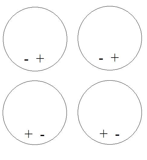
In the case of my amp, the arrangement would be:


#7
That sure does help. I got down there with a flashlight and the + / - arrangement on the speakers is literally the exact opposite of that  :dbtu:

So, I have a black and a white wire descending from the chassis.
On your diagram, I assume that my 'white' would be your red wire?
#8
Obviously I may be completely wrong but this strikes me as one of those old logic problems like they had on the college prep tests.

If that were the case, the answer seems as if it would be


Which only really leaves me with the shortened terminal to deal with, however there's enough there to solder to, if need be. I think I'll give this a try unless someone comes on and tell me it's a horrible idea and I'll be blowing up a perfectly good amp in doing so.  :lmao:
#9
There's got to be an elegant way to do this.

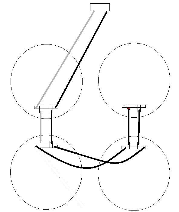
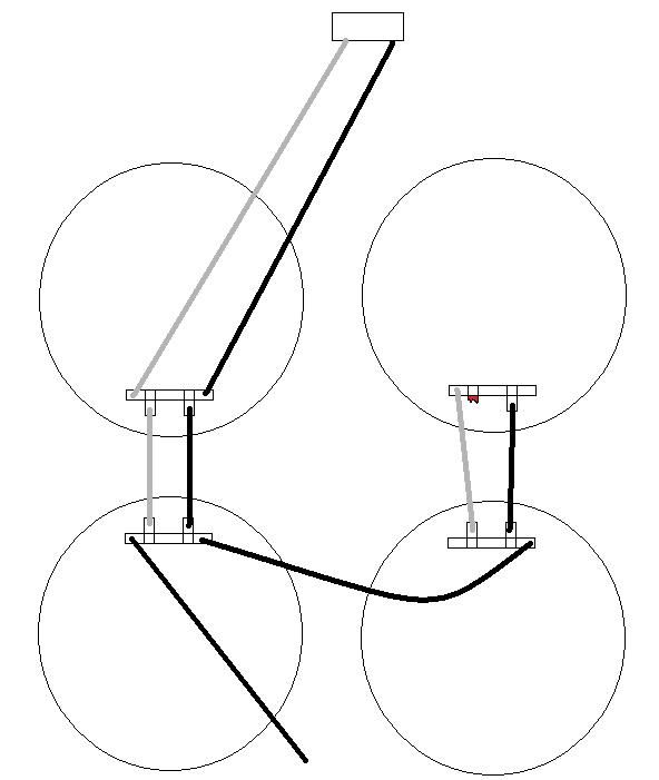
Here's the wiring scheme, as best my limited knowledge and understanding would allow me to draw with MS paint.


So, the black and white wire descend from the plug in the chassis and hook into the terminals as seen. Everything is sane and logical until the wire flowage goes from the left bank (which receives direct power input from the plug and is presently functional) to the right bank (which is presently non-functional and presumably, receives indirect power input from the left bank)

Here, we now have an erratic series of mish-mash wires twisted together, alligator clips, phantom colors...

For example, the white wire that flows from the plug to the top left speaker, another white wire to the bottom left speaker then becomes a black wire twisted off on the wire terminal and that is just dangling loose, connecting to nothing.

Anyone know the proper speaker wiring scheme here?
#10
OK, think we're home free.

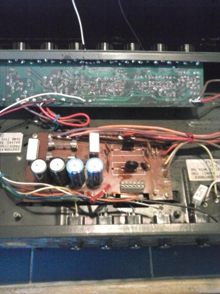
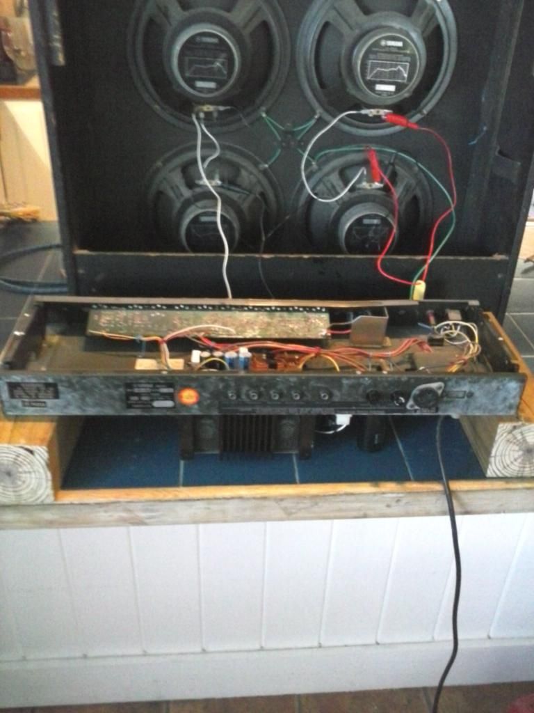
Took out the guts


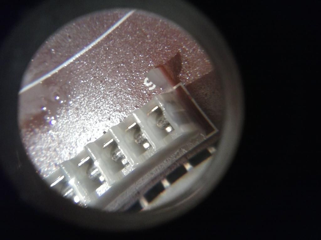
Turns out the pins for the power amp module weren't making good contact due to grime.

Here's my attempt at taking a pic of them through the lighted magnifier lens


Cleaned those, reassembled and now is consistently and reliably giving me full operation out of the left two speakers.

Anyway, now I have to wire up the two speakers on the right hand side.


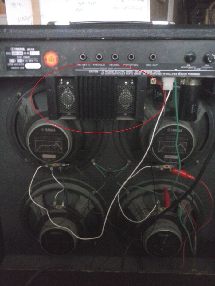
You can see the improvised alligator clip arrangement they were using, doesn't work. One of the tabs is broken off (top right speaker, etc).

How do I figure out what wire I need to buy, what little clips I need to get, etc?


#11
Thanks Roly  :dbtu:
I'm quite happy with it. Its late here and I didn't quite get to poking around in it today, but definitely will tomorrow and will post extensive pics.

@ Enzo

It was precisely as you said, removed those bolts, 6 pins, power amp module came off. Put it back on, amp stayed 'cut out' so the problem is definitely somewhere in the amp module itself or in the connection between the PAM and the board.

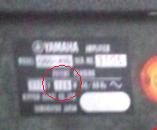
One thing I'm quite curious about; the chatter I read on the internet about these is extremely limited and fragmented, nowhere near robust enough to trust. Its said that the Fifty-410 is a 50 watt amp, however on the reverse of the amp, right here:


...it says 120 watt? It certainly is loud as all get out. Perhaps I'm confusing something, or perhaps the internet is confused?
#12
Good deal Enzo.
Will get to it ASAP.

The real problem here is that they put a tall and narrow 410 amp in a junior high school band class on casters. Incredibly, incredibly unstable arrangement that was meant for a frame, not wheels. Breathe on it hard and it threatens to tip over.

No doubt this puppy took a few spills and some connection got kicked loose.

I'll report back with pics once I start getting things taken apart.
#13
Well, here she is.
Decommissioned from a local junior high school bandroom closet, straight off a 20 year hiatus. I paid $85 for the amp plus $15 worth of fuel in the big V8 top go get it, so figure I'm in at 100 on this one, which I'm comfortable with at this stage. That leaves me budgeted $50 for parts before I'd get uncomfortable.

The intermittancy is coming from this.


When I tap it, I get signal. It was somewhat loose as far as the screws that held it to the chassis, I tightened them up but it's still causing intermittency and requires 'tapping' that specific part to get signal. Sometimes, when I turn the amp on, I get hum that dies out to clean after 5 seconds or so, tap on that a couple times, I get signal. Plays fine.

So, somewhere therein is the culprit. I'm guessing it's just a connection issue.

Where to start?

#14
OK lads. T- 10 hours and counting, picking up one of these.


... unsure yet if it's a 50w or 100w version, late 70's/early 80s 410 solid state with  intermittancy issues. Based on his explanation, mostly sounds like contact stuff. SS Jazzers are my weakness, these are very highly regarded from a tonal standpoint, the price is right for the relatively long drive so I'm diving in.

Prepurchase Question 1: Anyone familiar with these from a repair standpoint?

Prepurchase Question 2: Anything specific I should look for from a behavioral standpoint that perhaps should cause me to pass on the amp all together?

Presuming the amp is a go, I'll post further details here with detailed pics as soon as I get it home later this evening.
#15
Andy Brauer did an article in the 2009 issue of Vintage Guitar called "Sleeper Amps, part 1" where he talked about this amp and the heating issues. It's by no means an unconquerable quirk.

For the tone and volume they produce relative to their size, they're definitely worth working with. Always a bummer when there's a factory design flaw but sometimes, that can be a real goldmine for tinkerer types who can devise clever ways to remedy them and wind up with a great product, as these amps appear to be (based on my casual examination of them so far)

If I have to get to the point where I need to swap a trans, I'll go that way but so far, I've blown the doors out with it and it's run fine. Clean tone wise, I'd stand it against pretty much any other amp in its class. Once the heating issue is resolved, whatever it may lack theoretically in the design department, it makes up for practically with beastly sound.