Menu

Show posts

This section allows you to view all posts made by this member. Note that you can only see posts made in areas you currently have access to.

Show posts Menu

Messages - dazz

#61
Quote from: Katoda on January 30, 2018, 03:37:46 PM
:lmao: I wasn't expecting that at all  :)
If everything is securely in place and it won't move, then I guess it's OK. If the brown empty pcb is intented for the preamp, then you might have some mains hum when it gets amplified through it. Keep the input signal as far away as possible from that psu.
+1 for creativity  :)

Yes, that's where the preamp will go. I'll move the input jack farther away from the PSU and the PCB input will sit right underneath it, so the wire will be a few millimeter long, like 12 mm or so. Hope that works just fine. I guess I should have mounted the PSU with the mains facing the opposite side. Will fix that. Man, I appreciate your input, really do, Thank you!
#62
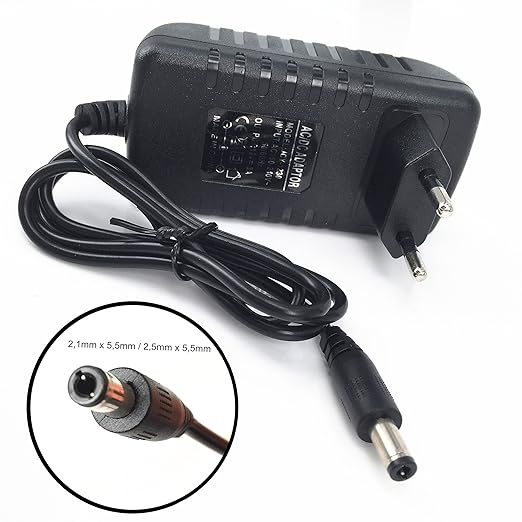
Oh, and here's a pic of the SMPS. Looks like it has a transformer indeed

#63
Quote from: Katoda on January 30, 2018, 10:55:15 AM
Crap, i was hoping there would be a cable... I wouldn't recommend mounting it inside the chassis, the coils would probably radiate too much for such a small enclosure. If the smps circuit has a transformer (as in - not just an inductor), you could fit in in another enclosure, one that would provide a connection to earth, but that's quite an advanced challenge, because you're dealing with potentially lethal voltages there.
If it's just a buck converter, there's nothing you can do but to buy another PSU. No mains isolation is a no-no.

Yes, the earth should be connected to the negative terminal, the ground.

Umm, not sure if what I did is safe then:


So I ripped the power supply, wired the hole thing with one lead from DC(-) to ground, wrapped the PSU in duct tape and mounted it like that. It works great but is that thing safe?
#64
Just to be clear, the mains earth should be connected to the power supply's negative DC output, right? I mean the sleeve of the DC jack
#65
Quote from: Katoda on January 30, 2018, 09:37:59 AM
Awesome, now that you know the source of the hum, you can take measures to eliminate it. It might be as simple as opening the hard drive PSU and connecting the chassis to the output ground, or as annoying as having to buy/build another PSU, if the current doesn't even have a 3-pronged mains cable.

If you are feeling adventurous, you could open the hard drive PSU, desolder the current 2-prong cable and replace it with a 3-pronged one, connecting the mains earth to the output ground (be careful if you do that, small mistake could mean a large fire and/or electrocution!!!)

Unfortunately it's one of those without a prong: the plug is integrated in the whole thing like this one:


What if I take it apart and mount the inner circuit inside my chassis with a mains ground connection? let's see what's inside....
#66
Quote from: Katoda on January 30, 2018, 09:01:09 AM
No problemat all, we're all here to learn :)

If the hum is mainly 100Hz-ish, the smps switching noise might not be the problem after all, since they operate at higher frequencies. If you get the power from a switcher, the ground is probably not connected to the "earth" connector of the mains. That would mean that you could be picking up mains noise from everywhere around you. Does the amount of noise reduce if you touch the ground with your finger? If it does, there's your problem. If not, the input might still be picking something from the mains, if it is not completely encased in grounded metal.

Yeah, it goes away when I touch the strings for the most part. The power supply is definitely not connected to main's ground. I guess it's time to look up a proper power supply?
#67
Quote from: Katoda on January 30, 2018, 06:50:16 AM
EDIT: The -3dB cutoff frequency of an LC filter is given as
f=1/(2*pi*sqrt(L*C))
So if the switching frequency is the same as the LC cutoff frequency, the power supply ripple will be 3dB smaller. Now, electrolytics have higher ESR and ESR, so for effective high frequency decoupling you want ceramics. A lot of them in parallel. Measure the coils inductance if you can, and then try to make the cutoff frequency a couple of times lower than the switching frequency.

I see what you mean now. I need a large enough inductor or else I'd need a crap load of caps. I have a tiny 0.05mH coil here that won't cut it cause I'd need 5000uF in caps to cut at some 100Hz if my numbers are right. I'll try the larger coil with all the leads in series as you suggested
#68
Quote from: Katoda on January 30, 2018, 06:50:16 AM
I didn't mean that it is better (or more usable for that matter) to have 4 conductor shielded cable, I just wanted to say what to expect. You can, however, use two or more of the conductors for the pots in the same signal path, like on a volume/gain pot - one pin is ground, and the other two can be soldered to different wires inside the cable. It just saves some space and results in a cleaner looking build, but the downside is that there is a lot of tension on the individual cores (if the plastic insulation is too thick), which might result in breaking wires.

Your cable wiring is correct, the shield is ground and the centre is the signal. You must watch for ground loops here, make sure that there aren't multiple connections to different grounds from any single point.

A choke is an inductor, a coil of wire wrapped around a magnetic material (ferrite, in this case). If the switching noise is really the problem, then try googling LC low pass filter. Because you dont know the coils inductance, it might be a hit or miss, but taking that toroidal psu coil and soldering some leads together, so it has all the wraps around the core in series and in the same direction, and then placing it in front of your amps power supply (so that it is followed by paralleled 1000uF and 100nF caps) might help a bit.

Keep the input of the power supply short and away from the preamp, as the switching from the external unit might be creating some quite strong EMI.

Awesome, thanks so much Katoda. I own one of these meters so I can measure the coils' inductance.

I still have no preamp in there, I'm using the Bazz Fuss pedal for the time being, but I'll move the supply input to the other side. I already have a hole in the chassis right where the power amp supply voltage input sits. Although I was planning to feed 12V to the preamp too instead of 9V for "máximum" gain so I'll need a wire from the 12V input to the preamp anyway...
#69
I've tried 1000uF, 100uF and .1uF between 12V and ground with no perceivable results  ???
#70
Quote from: Katoda on January 30, 2018, 04:06:39 AM
Yes, definitely use shielded wire. If you're a cheap scavenger like me you can reuse some old usb cables, they have good shielding and 4 cores.

Since you are using a hard drive (probably switching) power supply, you need to filter the hell out of it, using big electrolytics paralleled to small ceramics, maybe even throw a choke in ( you have some of these if you raided the computer PSU ). Otherwise there will be noise in the circuit. Perhaps you could even add in a small LDO voltage regulator for the preamp circuit to minimize the noise.

Cheap scavenger here too haha! That's exactly what this project is all about: reuse as much and learn as much as I can. thanks for those great suggestions. I ripped an RCA cable for some shielded wire, not sure how good the shielding is on this one but it didn't help too much. May I ask why would a 4 core cable be a better option than a single core one? I wired mine using the shield as ground and the core as hot. For what I could gather in my interwebz research that's how it's supposed to be done. Is that right?

Here's what's left of the PSU board, time to figure out how to build a filter for the power supply (I don't even know what a choke is LOL)

#71
I should probably go with shielded wire for the input right? Right now I'm using unshielded 22 AWG with silicon insulation
#72
Quote from: blackcorvo on January 29, 2018, 11:11:35 AM
Quote from: dazz on January 29, 2018, 09:43:13 AM
I have loads of hum and noise from the power supply though, a 12V 1.5A unit that came with an external hard drive

Time to check this out I guess: Topic: Grounding techniques

Perhaps if we see some pics of your build so far, we might see what's wrong. Also, measure the voltage of the power supply when you have the amp running, maybe the amp is loading the supply down.

With the Bazz Fuzz at maximum gain and volume and the power amp maxed out too I measured 12.1V, basically the same as unloaded.

Here are a couple of pics:


#73
I have loads of hum and noise from the power supply though, a 12V 1.5A unit that came with an external hard drive

Time to check this out I guess: Topic: Grounding techniques
#74
Thanks guys. They're dirt cheap too! Just ordered a bunch of them off of ebay for a couple €.

I already have the TDA7297 power amp installed and the component layout pretty much done. Driven by my Buzz Fuss pedal it's already usable (and quite loud but of course no tonestack) so I can have some fun playing while the preamp parts arrive in the mail.
#75
Quote from: blackcorvo on January 28, 2018, 08:02:29 PM
If you don't mind waiting, there are isolation washers you could try using for this:

https://www.tubedepot.com/products/isolation-washers-for-1-4-input-jack-flat-shoulder

If you'd rather not wait, or youc can't get that kind of washer, you could cut out a square in the chassis and use a plastic panel to mount the speaker-out jack to it. Or maybe a wooden panel, whatever fits the style of your build better.

Thank you, great stuff. Those washers look exactly like what I need. Problem is I'm in Europe and the $14 shipping fee is too much for such an inexpensive item, I'll see if I can find those somewhere else. If I can't I'll probably use a wooden panel

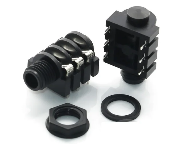
ETA: I think these connectors might work