Menu

Show posts

This section allows you to view all posts made by this member. Note that you can only see posts made in areas you currently have access to.

Show posts Menu

Messages - teemuk

#61
I don't think it's a good idea either. The extra coil is just an additional winding, basically to double power handling or just alter the overall impedance (depending wther you connect the coils in series or parallel).

The way I see it, both coils expect to see identical current flow as that is what magnetizes the voice coils and subsequently causes the former (and the attached diaphgram) to move in the magnetic field introduced by the permanent magnet.

And indeed it is possible to drive such speakers from different amplifiers assuming all these amplifiers behave identically, and in practice output the very same signal.

And as is the case as well with the more generic bridged and parallel connected amplifiers the hard part is ensuring that....

If the current flow in coils is unidentical, in worst case exactly opposite in both coils, you have excitation that draws, or tries to draw, the former into different directions. Like with power supplies, the stronger magnetic field would likely be dominant in this "fight" but the coil with lower current would be robbing "power" away from the stronger one and vice versa... At best this just introduces some distortion to the cone excursion, but at worst I would imagine there would be also somekind of flyback fed to the "redundant" coil, which would then directly affect the amplifier driving it. At worst detroying it completely.

I never tried this but I don't have disposable dual voice coil speakers and amplifiers on hand either. And I'm quite sure that for the experiment they would indeed have to be disposable.

Other than that, for the sake of experiment it might be educative. Like crashing expensive cars loaded with expensive crash test dummies into other cars or various obstacles. Educative in all kinds of terms, but I'd never give my very own stuff to test it because the generic consequences are kinda predictable: The cars and the dummy will be wrecked. Results of such experiments merely reveal how.
#62
- For 100W output, at least another pair of parallel output transistors
- Reliable and stabile therma-compensating bias circuitry. This will be difficult to realize properly because the output stage of that circuit has voltage gain and amplifies it's thermal instability.
- Emitter resistors to output transistors
- RC zobel to compensate inductance of the loudspeaker at high frequencies
- Some form of short circuit protection
- probably some close vicinity decoupling caps and high frequency feedback caps, depending on overall layout and stability of the circuit in such

...for starters. Though I have to say that I generally do agree with PRR, and you'd be better off building a good design from the start instead of trying to CPR a weak one that is obviously borderlining reliability and stability.
#63
Tubes and Hybrids / Re: New Single End Amp
April 26, 2014, 02:11:07 PM
QuoteA tonestack placed ahead of a clipping stage changes which frequencies clip first/hardest.

A tonestack placed after a clipping stage changes which newly generated harmonics are enhanced or reduced.

Spot on!

The generic tonestack, however, often introduces nothing but "low Q" high-pass, band-pass/band-reject, -and low-pass filters at specific frequencies of interest. They may be fit for overall tone correction but overall their magnitude still tends to be rather low.

With a simple design, that merely switches between gain stage + gain stage + EQ and gain stage + EQ + gain stage -structure, you may find equalisation provided by the EQ alone insufficient enough that performance of these two inherently different "modes of operation" are somewhat compromised.

For example, without excessively applied hi-pass filtering before clipping distortion the resulting clipping may not be "tight" enough or it will sound too "fuzzy" while user's preference happens to be closer to more "modern" overdriven tones. If such hi-pass filtering correction is added then "cleaner" mode of operation becomes excessively "bright" and "thin". The natural low end is lost.

As entire amp design practically relies on pre and post distortion shaping you can imagine how much is compromised when simplicity is the goal and the task of "voicing" is practically solely left on shoulders of the EQ, which is often nothing but the simple tonestack.

Have you ever seen frequency response of a generic "cleanish" amp versus generic O/D channel of a modern amp? The effect of the tone control in the entire picture is surprisingle small in the latter.
#64
The Newcomer's Forum / Re: behringer GMA 100 miniamp
April 24, 2014, 10:07:45 AM
QuoteAs you have found, only Behringer would have the audacity to say an amp that runs on 9V and fits in your pocket has "classic guitar sound!"

It's called "advertising".

Behringer is doing the same thing what every other company in the business is doing. Ever looked how companies like Marshall or Vox advertise their products similar to this battery-powered Behringer amp?

"Packing full Marshall tone".... "For those players for whom a full stack is a must"  :lmao:
(Quotes taken from Marshall MS-4 / MS-2 amp advertisement)


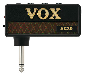
"Signature AC30 Top Boost Tone"  :lmao:
(Quote from Vox Amplug AC30 advertisement)


Quote"Original vintage-design guitar speaker"

Reminds me of Fane speakers mysteriously becoming an "improvement" to previous Celestion speakers of AC30. Noooooo.... couldn't possibly have anything to do with the company that owned Vox trademark at the time being also the UK importer of Fane speakers. Que 10 years forward and suddenly the "painstakingly recreated" Celestion speakers are the right speaker choice for the AC30 again....  :lmao:

QuoteThis chip amp has a power output a bit over one watt.

Well, that's amazingly in the same ballpark of output power as certain single-ended, cheaply manufactured, well over $700 costing Marshall amps that are supposed to sound exactly like their 50W - 100W push-pull counterparts.   ::)

That is, if you like to blindly believe in advertising.
#65
QuotePlease explain WHY do you edit MY posts without asking? :loco

Sorry. I was meant to quote it but I accidentally seem to have pressed the modify instead. I noticed the accident only was I had sent the message and started to wonder why the new post didn't show up. At that point it had already been "edited". The only edit to it is that I removed my post from the bottom. Once again, I'm sorry for this.
#66
QuoteFWIW that crazy schematic shows the speaker with a wire ***shorting*** it
i think the JWOPT = "Jumper Wire, Optional" -remark might have something to do with that. They use the same boards for many different amps, perhaps one is a head and benefits from short circuiting terminals that, without an internal speaker connected, would provide no continuity to following interconnects like headphone or external speaker jacks.

Or maybe they just build it like it is and there's a giant batch of Crate amplifiers that self-desctruct when you plug them in. Come to think of, I never heard of such thing.  ::)
#67
inch = 25.4mm

Typical component lead diameters are 0.63 mm, 0.7 mm and 0.8 mm (for ordinary components, 0.7 mm being most common), 1 mm (high power resistors and transistors) and 1.5 mm (trimmers, potentiometers etc.). Usually the biggest component leads are rectangular instead of round.

So basically you need a set of different sizes of bits. Use the one matching closest to component lead diameter.

And yes, they break very easily without a drill press. In fact, they break so easily that I wouldn't even dream of drilling the PC board without one.
#68
The limiter itself may obscure some tests with the amplifier because, after all, it limits current. And it limits current whether the amplifiers is broken or in perfect working order. With the bulb there the amp, for example, will not reach its maximum output power because current limiting kicks in harder the harder you load the amp.

I basically go with the light bulb's dimness (or brightness) in the idle state of the amp as a sole indicator. If it's dim a chance is the amp works fine. If it's bright the amp is short circuited or at least drawing significant amounts of current (e.g. oscillating output stage).

Current draw shouldn't be excessive when the amplifier is in idling state (except in class-A amps, which are an example of one of those devices which's operation a light bulb limiter may obstruct a big time) so if the bulb is bright when the amp idles it's usually a sure sign of problems. Dim is fine, the amp is always drawing a bit of quiescent current. A high power amp with many parallel transistors may in fact draw lots. Amp biased hotter naturally draws more than amp biased colder.

If in doubt, then you can always take measurements of the circuit with multimeter. Excessive quiescent current draw? Voltages out of place / not right at some places in the circuit. Any other obvious signs of faults that may not cause excessive current draw to which the bulb would react?

There's basically not a "yes or no" -answer we could give based on the bulb itself, other than that when it's dim we know the amplifier isn't drawing excessive current at the moment. Note those words. The bulb doesn't clearly indicate faults that have to be "triggered" somehow, like output clamping to one of its rails during clipping, or oscillations starting in condition x. The bulb just indicates whether the amp is or isn't drawing excessive current. At the moment. That's all.

You have to advance from that point with other means. Whether they are trusting you fixed the amp completely, getting rid of the bulb and testing the thing (e.g. with "plug and play" method), or keeping the bulb and making further measurements in an attempt to pinpoint other possible issues. Most likely when the bulb is dim it can be removed and you can still perfrom the second option. You get more "accurate" results then too because the bulb is out of the circuit.
#69
Tubes and Hybrids / Re: My Attempt at a Hybrid Design
February 28, 2014, 08:30:37 PM
Quotespot where the VCC trace passes under the IC, which much be smaller to pass between the pads. How big of a problem will it be to make it thinner at this spot?

Think of the currents involved.
The VCC trace that passes under the IC needs to withstand only the current draw of Q1 and its biasing circuit. That is few milliamperes at best.
The VCC traces that supply the power amp IC, and traces that run from TDA2050 output to speaker (return path of speaker's "ground" current included) on the other hand must carry currents in excess of 3 or 4 amperes, maybe more! Remember that internal limit of that chip is as high as 5 amperes.

You don't need to thicken all traces, just those ones that count. Basically the higher current the trace carries the thicker it must be. Thin trace = resistance, you don't want to mix that with high currents because the way that resistance dissipates its waste power is by heating. I'm sure a few minutes of google searching will find equations to calculate proper wire diameters / trace widths when currents are known. You probably don't have to care about that sort of stuff with the low current buffer in front, but in power amps that start to handle very, very high currents this becomes a very important design aspect. For same reason also proper routing of currents becomes important: you don't want amperes of transient current spikes return through the reference point of small signal stages.

Anyway, thickening all traces usually just introduces more drawbacks. Low current stages work well with thinner traces and thinner traces allow keeping more distance to traces that you don't want to "crosstalk". Basically every trace or wire running in parallel with another forms a tiny, tiny capacitor. Especially with high impedance circuitry ( >100K ) even very low capacitances start to mean a great deal. Picture a trace carrying the signal running a long way in parallel to ground trace, the capacitance might cause attenuation of higher frequencies. You can use this effect for your benefit too: Power supply traces benefit from running as close to their corresponding ground return traces.

Also, every trace and wire has inductive characteristics as well as a little magnetic field around it. Proper trace distance also helps eliminate interference from such in delicate circuits where tiny details like this begin to matter in utmost importance. For example, when frequencies involved rise above several hundreds of kilohertz's the series and parallel resistances, inductances and capacitances of the board design must be taken into consideration as real electronic components. Thank goodness guitar amp design doesn't focus much above 10 kHz.
#70
Tubes and Hybrids / Re: My Attempt at a Hybrid Design
February 28, 2014, 05:19:07 PM
Think for a while about currents that those traces will be carrying... You seriously need to consider thickening up some of those traces.

I like how the ground currents properly return so that higher currents do not have to return through stages with lower currents and much more sensitive inputs. Audio and power ground returns also seem to have fairly good separation. Local filtering caps are also nicely close to terminals of the IC but their layout and "noding" might need a few tweaks.

1st, that (probably 100nF or close) filtering cap (C5 I presume) should be as close to VCC terminal of that IC as possible. It's job is to act as local filter cap that counteracts the tiny tiny inductance of the power supply wiring. Placed too far away from IC's terminals its effect to do this becomes negligible. It must be placed close so it can do its purpose properly. The higher capacitance filtering cap can be further away but minimising length of power supply wiring (including traces on circuit board) is always a good practice. Now let me remind you about that adequate trace thickness. Several amperes of current will flow in some of those traces!
2nd, it's not really good "noding" to "T" capacitors. If you think about it, you want charging currents to flow to the terminals without much interference with currents pulled by the load. If you "T" the traces going to the capacitor's terminal both currents are forced to share their paths. If you just wire everything directly to the terminal, without that little "sideroad" to terminals, the current loops will have much less paths of interference. The same logic naturally applies to both terminals, positive and negative. Remember: current flows are loops.

Overall, I wouldn't etch that PC board just yet. Give it a few days of further thinking. You'll have much better success in building a flawlessly operating amplifier.
#71
QuoteI'm not quite sure... this is a 'modelling amp'

The Valvetronix amps are hybrids of digital and analog modeling. The preamp employs digital modeling, DSP and algorithms, the power amp employs analog modeling aided by digitally-controlled switches: different preamp patches also control switches in the power amplifier circuit. The DSP models preamplifiers and associated effects, the analog circuit integrated to the power amplifier models the operation of a push-pull tube power amplifier.

Quote..and those switches just seem to short out a 15K resistor feeding the grids of the valve...!

Well, they basically toggle an attenuator: resistive voltage divider formed by R23 & R24 and R27 & R28. Resistances R20 and R21 are low enough to be somewhat insignificant.

Why attenuate? Follow that switching logic a bit forward: the same switching "bus" also drives a switch that toggles the negative feedback loop that goes from tube stage's output to inverting input of the differential input stage. When feedback loop is disabled the gain is higher and input is respectively attenuated to compensate this.

Follow a bit further and you notice that the whole "bus" is driven by inverter built around transistor Q8. From it's base circuit you find another switch logic "bus", which in addition to aforementioned inverter also controls the A/AB bias switching circuitry (circuit around Q4 & Q3 varies cathode resistance of the dual triode, Q3 is basically a switch that connects R41 in parallel to R42).

I'd start by verifying that this entire logic circuit works as intented and that ALL switches in it work. e.g. permanently "stuck" negative feedback could cause excessive attenuation of the signal.
#72
Amplifier Discussion / Re: My K-20X
February 28, 2014, 07:30:36 AM
I see the PC board is used for other, more feature packed, amps of that series as well. Have you thought about building those unpopulated areas in the printed circuit board? What's omitted by the way? I reckon at least spring reverb driver and recovery stages...?
#73
Agree with Phatt. Test supply voltages to rule them out as fault source, and test DC reference bias circuits to the PA chip assuming there are any. Without knowing details of the design its hard to point out what else to test before just shotgunning the chip, but chip failures are rather common and replacements cheap so its likely the path of least resistance to sub in a fresh one while keeping thumbs up. If it fails then it obviously needs some rethinking. That time the bulb limiter will likely save the fresh chip, though.
#74
Amplifier Discussion / Re: Jordan Entertainer J110
February 18, 2014, 06:38:11 AM
How "wrong is the schematic"...? Few minor circuitry revision changes excluding a rather helpful reference? Or entirely unusable?

It would help tremendeously if we were even slightly familiar with what kind of circuit we're dealing here. Is it possible for you to scan or photograph the schematic and post the image here?
#75
QuoteIf you want more power into a given load then you first need more voltage, then maybe more devices to handle the higher resulting current.

Right?

Power is a function of both voltage and current. A successfull design needs a proper reserve of both.

Yes, voltage is needed. There is no question of that.

BUT... current is also needed. If the power supply can't provide enough current the power supply voltage sags.

So that brings us again to having less voltage for the amplifier to do its thing. That's the reason why supply voltages are sometimes indicated in both unloaded and loaded conditions.

See where this is heading...? Theoreticallt you could build an amplifier that could supply all the current in the world but that amplifier isn't magically creating that current. It's just a "valve" between the power supply and the load. Ultimately it all falls down to power supply and its capabilities.

So your amp has too low supply voltage to produce 100 watts across 4 ohms? Well, use 2 ohms. There's your supply voltage restriction.

So your power supply can only provide 100 milliamps of current? Yeah, let's see what you can do to that.