Menu

Show posts

This section allows you to view all posts made by this member. Note that you can only see posts made in areas you currently have access to.

Show posts Menu

Topics - Roly

#1
Amplifier Discussion / "Where's Roly?"
July 28, 2015, 04:05:31 AM
{The Last Post - there is no right place to post this, but to save cluttering up the Limiting Lamp tread...}


Since the question has now been asked...

In May I was diagnosed with terminal lung cancer.  It has taken a rapid toll on my energy level and I've had to clear the decks and savagely triage my various activities, pass on my baby OzValveAmps.org, drop out of forums, and focus on family and friends in the estimated 6 to 24 months left to me.

"Where there is life there is hope", certainly, and I'm getting excellent and intensive cutting edge care from the best oncology unit in the State, but realistically, I'm not walking away from this one, so my partner and I intend to have the best time possible in what remains.

While I'm still very weak the team have already restored some of my strength and feel that they can restore enough for Bev and I to take a last farewell road trip to visit old muso friends, to have slap up dinners, to play, sing, laugh, cry, and move on.

Rest assured that I'm not in any pain, and that I am mentally composed about the situation.

So thanks for all the interactions and problems to solve, it has been an enjoyable trip.  I'll still be dropping by to see what's happening, but I won't be posting much, if at all.

Cheers,

-Roly
#2
Amplifier Discussion / Farfisa TR60 Transicord Amp
December 02, 2014, 02:34:40 AM
Farfisa TR60 Transicord Amp

Circuit, user/service manual, anything needed.
#3
Amplifier Discussion / Fender Frontman 65 distortion
December 07, 2013, 04:45:05 PM
Okay, now I need some help.

I have someone writing to me who has been struggling for weeks with an odd fault on a Fender Frontman 65.  After very extensive checking of all the usual suspects it comes down to this; the amp randomly starts distorting, and when a meter probe is lightly touched on to TP20 (join of D23 and D24) it suddenly comes good again.

I now suspect high frequency instability of some sort, possibly due to an aging component such as a bypass cap, but I'm wondering if any of the brains trust has encountered this before and has any clues.

cct attached
#4
The Newcomer's Forum / Java 7 Update 11 Warning!
January 16, 2013, 08:58:37 PM
In the last couple of days a second "zero day exploit" has been found in Java 7 Update 11.

DISABLE Java in your browser, and if it isn't vital to your operations uninstall it altogether.

Read more;
https://www.google.com.au/search?q=java+7+0+day+exploit

:grr
#5
Quote from: joecool85 on May 03, 2012, 11:52:55 AM
Quote from: Roly on May 02, 2012, 11:27:30 AM
Here's my indicating proportional "thermofan" design that has been used in several amps including a re-creation of an Acoustic 360 by J.C.Maillet;

http://www.ozvalveamps.org/techsite/thermofan/thermofan.htm

VERY cool!  If you don't mind, I'd love to have you start a thread here about this and include schematics, diagrams, pictures, whatever you can.

Ho-kay.


Design starts with a problem, and in this case the problem was a small home-brew PA that had been dropped on me to fix because it "has a couple of problems" and "doesn't work very well".  These would soon turn out to be major understatements.

The mixer portion needed a serious scrub up, mainly replacing 741's with TL071's, but the power supply and power amps were such a misbegotten mess that the only option was to totally rebuild them in a different case.  Since it was a "love job", to keep costs down the metal case from an old gutted VHS VCR was used.

The original unit didn't have a heatsink worthy of the name, about a square foot of 1/16" ali flashing screwed down to the wooden case floor, so again the workshop junk heap provided a length of pre-loved real heatsink.  But as the rebuild was coming together it became obvious that the heatsink would have to go inside the VCR case - somewhat less than ideal.

This in turn meant that the heatsink would need to be blown by a fan (again, dragged out of the junk pile), but the amount of noise it made led to a long ponder.  What was really required was some way of controlling the fan so that it provided cooling in proportion to the need.

A search of the InterWeb turned up any number of "bang-bang" or on-off fan controllers ranging from highly dubious to elegant overkill, but no proportional controls.

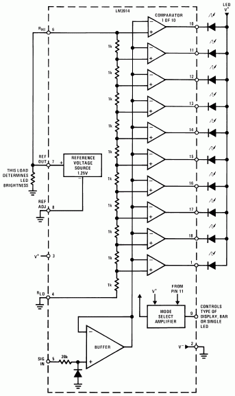
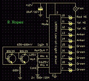
I eventually concluded that I would have to roll my own, and decided on using silicon as temperature sensors combined with a linear LM3914 "Dot/Bar Display Driver" (aka Line-Of-Light driver) as the heart of a proportional fan controller.  In bar mode the accumulating current drawn through the LED's could come via a fan, giving proportional current control.


The Controller


I chose this IC because its input side is floating and can be referenced over a wide range of zero and span settings; and because the LED driver outputs are programmable current sinks that can also be easily set anywhere between 2mA/step and 30mA/step.

This current mode output is an important property since it makes the circuit quite insensitive to supply voltage variation, and means the indicating LED's can be left out or doubled up (or more) in series, and that a second fan can be used in series on a supply up to 25 volts without any circuit changes.

The LM3941 has a stabilised reference voltage output of 1.250V available which is used to energise the zero point and span point settings, and in this case provide a stable bias voltage for the temperature sensor.

The zero and span are set by two twenty-turn trim pots in series, and while ordinary trim pots will work their setting is quite sensitive and tends to be a bit fiddly.  These are tweeked pretty arbitrarily so that only the first LED or two come on when idle at a moderate ambient temperature, and that the last LED comes on when the heatsink is getting too hot.

In this IC the reference output also doubles as a setting for the output current sinks which each sink ten times the current flowing out of the reference output.  Here the output current was set to about 20mA/step which relates to full fan current of 120mA a bit over half scale.

This current is set firstly by the value of the zero and span pots themselves - at 500 ohms each they present 1k ohm to the reference, drawing 1.25mA and therefore setting the output current to ten times this current; secondly the temperature sensor draws roughly another 1mA, so the overall setting is around 20-25mA/step.


The Sensor

One of the properties of a silicon diode is that it has a temperature co-efficient of about -20mV -2.1mV per degree C, that is the "on" voltage falls by 20mV -2.1mV for every degree C it gets hotter, and it's pretty linear from 0 to 100 degrees C.  Since the base-emitter junction of any transistor is also a diode, and since some transistors come in packages with handy screw holes, and since we don't need to know accurately what the temperature actually is, a specific temperature sensor IC isn't required.

I used a couple of BD139's because I wanted to monitor the temperature of both the power transformer and the heatsink, and they were to hand.  The mounting hole made them much easier to attach than ordinary power diodes (such as the EM410, 1N4001, etc) which are another option.  These two were connected in parallel so the hottest one rules, and there is no reason why this couldn't be extended to monitor several points if desired.

It is also possible to stack diodes or transistors in series to get a larger voltage swing with temperature if tighter control is needed, 2 = -4.2mV/C, 3 = -6.4mV/C, etc, but just for amp cooling applications I have only used a single diode drop and found that sufficient.

This voltage is input to the LM3914 on its "Sig In" line.  Because the collector and base of the temperature sensing transistor are held at the reference voltage (1.250V) the emitter voltage rises from 1.25-0.65 = 0.6 to 1.25-0.6 = 0.65 volts over the temperature span.  The Zero or RLO input is set for around 600mV and the Span or RHI input set for around 650mV.


The Display

The LED display is actually optional, 'tho I would at least include it inside for diagnostics even if not mounted on the front panel.  There can also be more than one display if the LED's for each step are wired in series.  I have used a range of LED's from dull green. bright green, through amber, brighter orange, to red and very bright red.  At typical on-stage distances it is difficult to see how many LED's are alight, so the change in colour and brightness give a good indication at a distance of how hot things are running.


The Fan

The fans used have been the modern electronically commutated type, nominally 12 volt at 120mA, but there is no reason why a brush-type fan could not be used.  These particular fans were recovered from dead PC power supplies scrounged free from local computer repair shops (and 'tho normally filthy, full of still useful bits).

The fan voltage is the main limitation to the supply voltage for the controller since the LM3914 itself will work up to 25V, so two 12 volt fans can be used in series if desired.  This circuit should also be capable of running two fans in parallel although this hasn't actually been tried, and it is worth noting that experiments indicate a rule of thumb that fans provide 90% of their cooling effect in the first 10% of their rev range -  a little draft has a big effect, and the law of diminishing returns sets in early.

In the event that electronic noise from the fan operation gets into the audio circuitry an electrolytic cap of suitable rating, say 100uF/25V, can be placed directly across the fan.  Similarly with the control circuit itself, although in practice the switching between segments is so slow that no "zippering" noise has been evident (as it sometimes is in VU meter applications of this chip).


Supply Voltage

Naturally if 120mA at 12 or 24 volts DC is available then supply is easy, but in practice it has been necessary to use a three pin regulator and supply side dropping resistor from the main amp positive supply rail.  The exact arrangement depends on what is available in each situation.


Construction

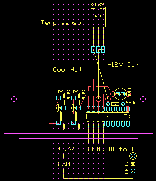
Construction is quite non-critical and has been normally done on strip or dab board, with the LM3914 and trim pots mounted on one board, ribbon cable to the LED's mounted on another board on the front panel, and the temperature sensors on flying leads and suitably insulated with heat-shrink.  A fairly important point is that the zero and span setting trim pots are accessible with the circuit mounted in place.

Here is one possible layout that I've used;


{errata - LED shown in wrong direction}

Operation

In operation the fan generally doesn't start rotating until things have warmed up a bit and three or four LED's are alight.  Once started however the fan will continue to run from very slow to full speed depending on the temperature.  In use it was found that something pretty gross had to be done to get the top LED's to light, such as driving the amp hard with a towel blocking the air paths.


Extras

A possibility that hasn't been tried is to use the highest indication as a thermal cutout or limiter as last-ditch amp protection.  This could be done by including an opto-coupler in series with the hottest LED to limit or mute the audio drive, or to operate a relay as a supply cutout.


Acoustic 360

When applied to the re-creation of the Acoustic 360 bass amp by JC Maillet it was desired to run three fans and this required the modification of the output circuit so that they were run via current mirrors.


In summary, this simple circuit has proven very effective in providing fan assisted cooling in solid state amplifiers, while minimising fan noise problems.


Add: 120729
Thermofan test in Acostic 361+ clone build
http://www.youtube.com/watch?v=ptxIJlRUrNw