Title: Just built a Tone Bender Mk.I . Need advice.
Post by: LJN on January 06, 2016, 04:14:45 AM
Post by: LJN on January 06, 2016, 04:14:45 AM
Hello, all. I got tired of dreaming about it, so I went ahead and wired up a Tone Bender Mk.I. It's working and has plenty of sustain, but it's awful dark sounding. Are my transistors' hfe too low?
Title: Re: Just built a Tone Bender Mk.I . Need advice.
Post by: J M Fahey on January 06, 2016, 09:49:46 AM
Post by: J M Fahey on January 06, 2016, 09:49:46 AM
Post-the-schematic d*mmit !!! :trouble :lmao:
How are we to even guess otherwise?
How are we to even guess otherwise?
Title: Re: Just built a Tone Bender Mk.I . Need advice.
Post by: LJN on January 06, 2016, 05:00:20 PM
Post by: LJN on January 06, 2016, 05:00:20 PM
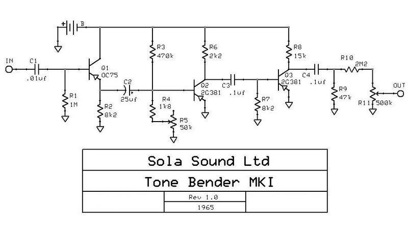
I don't have any way of posting the schematic. The one I built is the Sola-Sound. I used all the stock values on the resistors. The caps are the stock values, except for the electrolytic. I used an axial lead 22 uf. The transistors are AC128 with the and leakage as follows: Q1 hfe 60 with 0.10ma leakage, Q2 the 73 with 0.06 ma leakage and Q3 hfe 62 with 0.06 ma leakage. There's a hissing noise in it and it has way too much low end.
Title: Re: Just built a Tone Bender Mk.I . Need advice.
Post by: LJN on January 06, 2016, 10:19:09 PM
Post by: LJN on January 06, 2016, 10:19:09 PM
Okay, so I've reduced the low end response by changing the 470 k resistor out for a 180 k. It's much brighter sounding now and gets close the Yardbirds- era Jeff Beck sound. There's still a problem with the note decay. As the signal fades, there's a sizzling noise. Is it supposed to do that? There's also a bit of hiss when there's no signal going in. Do I need to swap Q3 for one with more leakage? The effect is also pretty gated at maximum attack setting. Is this also a leakage related problem?
Title: Re: Just built a Tone Bender Mk.I . Need advice.
Post by: phatt on January 07, 2016, 12:44:24 AM
Post by: phatt on January 07, 2016, 12:44:24 AM
What JMFahey said 8|
Meantime this covers most of what you need to know.
http://revolutiondeux.blogspot.com.au/2012/03/sola-sound-ltd-tonebender-mki-hornby.html
Phil.
Meantime this covers most of what you need to know.
http://revolutiondeux.blogspot.com.au/2012/03/sola-sound-ltd-tonebender-mki-hornby.html
Phil.
Title: Re: Just built a Tone Bender Mk.I . Need advice.
Post by: LJN on January 07, 2016, 01:59:33 AM
Post by: LJN on January 07, 2016, 01:59:33 AM
Okay. I can't post the schematic. I'm doing this from my phone and it keeps saying "low memory". I really hate modern technology. It's the Sola-Sounds LTD. version.
Title: Re: Just built a Tone Bender Mk.I . Need advice.
Post by: LJN on January 07, 2016, 03:36:23 AM
Post by: LJN on January 07, 2016, 03:36:23 AM
Does anyone know the correct voltages for this circuit? I checked them on mine and here's what I got. With attack on zero : Q1- C:-9.61v, B:-1.80v, E: -2.31v. Q2- C: -7.47v, B: 0v, E: 0v. Q3- C: -6.47v, B: -0.02v, E: 0v. With the attack control on full, here's what I got. Q1- C: -9.60v, B: -1.59v, E: -2.05v. Q2- C: -0.13v, B: -0.14v, E:0v. Q3- C: -6.81v, B: -0.03v, E: 0v. Are these even close to being correct?
Title: Re: Just built a Tone Bender Mk.I . Need advice.
Post by: J M Fahey on January 07, 2016, 10:17:10 AM
Post by: J M Fahey on January 07, 2016, 10:17:10 AM
How did you build it without the schematic? ???
Title: Re: Just built a Tone Bender Mk.I . Need advice.
Post by: LJN on January 07, 2016, 02:38:05 PM
Post by: LJN on January 07, 2016, 02:38:05 PM
I have a schematic on a piece of notebook paper. It's just that my phone won't post an image on here. I tried last night. I saved an image of the schematic on my phone and it just won't let me post it.
Title: Re: Just built a Tone Bender Mk.I . Need advice.
Post by: LJN on January 07, 2016, 03:25:16 PM
Post by: LJN on January 07, 2016, 03:25:16 PM
I give up. This stupid phone won't do what it's supposed to.
Title: Re: Just built a Tone Bender Mk.I . Need advice.
Post by: LJN on January 07, 2016, 10:46:57 PM
Post by: LJN on January 07, 2016, 10:46:57 PM
I've been trying to get a schematic posted on here, but I can't. If someone could just recommend some acceptable voltages for a Sola-Sound Tone Bender Mk.I , it would really help alot. Thanks.
Title: Re: Just built a Tone Bender Mk.I . Need advice.
Post by: g1 on January 08, 2016, 12:03:35 PM
Post by: g1 on January 08, 2016, 12:03:35 PM
Is this schematic close?
http://s292.photobucket.com/user/ledzeppy/media/Tone_Bender_MKI.jpg.html
http://s292.photobucket.com/user/ledzeppy/media/Tone_Bender_MKI.jpg.html
Title: Re: Just built a Tone Bender Mk.I . Need advice.
Post by: LJN on January 08, 2016, 04:10:41 PM
Post by: LJN on January 08, 2016, 04:10:41 PM
Yes, that's the one. Identical to the one I have in my binder. Thank you.
Title: Re: Just built a Tone Bender Mk.I . Need advice.
Post by: phatt on January 09, 2016, 09:26:50 PM
Post by: phatt on January 09, 2016, 09:26:50 PM
You need to do some reading if you want this to work.
I've already linked this; http://revolutiondeux.blogspot.com.au/2012/03/sola-sound-ltd-tonebender-mki-hornby.html
And I quote from that page;
Now, before you have a go at this there's a few things you need to know - the MKI ~Tonebender is a right bugger to build, it's the most tempermental circuit I've ever messed around with. However, if you get it right the rewards are worth it. For more info and biasing tips check out this article on Geofex: http://www.geofex.com/Article_Folders/zonkmach/zonkbst.pdf (I know it's for the Zonk Machine but they are the same circuit!).
The PDF covers all this in detail,, Obviously the circuit is a royal PITA and even if you get it to work on the test circuit it may not work so well afterwards. Obviously there is no *Right bias voltage* as the whole circuit is component dependent so you will have to find that by trial and error.
I read once that if you put the circuit in the fridge for a while it changes the bias effect.
If that be true then I have NO desire to build one,, positive ground as well can present issues with other pedals. HINT 8|
I think mictester over at FSB commented on these germ circuits way back and noted that the silicon version is the better bet,, far more stable.
One other point regarding residual fizz on decay,
Be aware that modern amplifiers often have much wider bandwidth and that will accentuate the fizz.
Old classic Valve amplifiers often had limited bandwidth and hence the fizz was less intrusive.
Phil.
Title: Re: Just built a Tone Bender Mk.I . Need advice.
Post by: J M Fahey on January 10, 2016, 03:29:17 AM
Post by: J M Fahey on January 10, 2016, 03:29:17 AM
You are talking this:
(Photobucket goes to great lengths to hide or obscure direct picture links, so you are forced to view them inside their ad loaded site)
Schematic comment: ugh !!!! :duh
They don't even care to bias, transistor losses take care of that :loco
So no 2 units will sound the same (sorry Zepp fans :( ) , they will vary wildly according to weather (literally) and looks like you have to carry both a Thermos with boiling water and some ice in a portable expanded polystyrene fridge just to fine tune it?
Yummy !!!!!!
As mentioned by Phatt, there's no real guarantee that it will sound anywhere close to Jimi's and on a modern amp it may sound fuzzy.
Those old Silvertones often were dark and muddy (that's an understatement) ... proof enough is that a normally bright and jangly Tele was used ... and nobody noticed it until it was published :duh
Title: Re: Just built a Tone Bender Mk.I . Need advice.
Post by: LJN on January 10, 2016, 07:01:29 AM
Post by: LJN on January 10, 2016, 07:01:29 AM
Thank you for your replies Phil and Juan. I have it working much better now. It turns out I had accidentally placed the electrolytic cap backwards in the circuit and that was driving me crazy. I didn't notice until I had swapped every resistor (except the 2k2). It's now getting close to that Yardbirds sound, but it could do with some higher gain transistors. I want it to be more buzzy sounding. I'm. Pretty sure that Mr.Page used a professional Mk. II bender. I'm also working on one of those and it's giving me more problems than this Mk.I, if you can believe that. As usual, the amp I'm using is my early 70s Kasino. Thanks to Juan's suggestions, among others, It's still working. These tone benders are certainly teaching me a lot about germanium fuzz. Thanks again.
Title: Re: Just built a Tone Bender Mk.I . Need advice.
Post by: LJN on January 10, 2016, 07:05:36 AM
Post by: LJN on January 10, 2016, 07:05:36 AM
Oh, and I was blaming those poor AC128s for the muddy sound. After fixing the cap problem, it's now very bright sounding.
Title: Re: Just built a Tone Bender Mk.I . Need advice.
Post by: phatt on January 10, 2016, 07:39:01 AM
Post by: phatt on January 10, 2016, 07:39:01 AM
Cool :tu:
Regards posting pictures I have been using this;
http://postimage.org/
Specifically aimed at forums,, Heck if I can work it out it must be close to dumb proof :lmao:
had no major issues so far. :tu:
Phil.
Regards posting pictures I have been using this;
http://postimage.org/
Specifically aimed at forums,, Heck if I can work it out it must be close to dumb proof :lmao:
had no major issues so far. :tu:
Phil.
Title: Re: Just built a Tone Bender Mk.I . Need advice.
Post by: LJN on January 10, 2016, 07:04:56 PM
Post by: LJN on January 10, 2016, 07:04:56 PM
Thanks. I'll give that a try. Don't know if it'll work with my phone. I took a look and it seems a but confusing to me.
Title: Re: Just built a Tone Bender Mk.I . Need advice.
Post by: LJN on January 10, 2016, 08:50:21 PM
Post by: LJN on January 10, 2016, 08:50:21 PM
I can't figure that pos image thing out. It says something about copying the text. I guess I'll just stick to what little bit I can actually do on here. Thanks anyway.
Title: Re: Just built a Tone Bender Mk.I . Need advice.
Post by: J M Fahey on January 11, 2016, 12:33:22 AM
Post by: J M Fahey on January 11, 2016, 12:33:22 AM
Just thinking aloud: can't you leave the phone aside for a while and grab/beg/rent/steal ;) a PC/notebook/netbook/tablet for a few minutes?
Phones are cool and available anywhere but sometimes not enough for some tasks.
And not sure how well you can see schematics on the tiny screens anyway.
Phones are cool and available anywhere but sometimes not enough for some tasks.
And not sure how well you can see schematics on the tiny screens anyway.
Title: Re: Just built a Tone Bender Mk.I . Need advice.
Post by: LJN on January 11, 2016, 05:41:56 AM
Post by: LJN on January 11, 2016, 05:41:56 AM
I can see schematics just fine on it. I just can't get it to post an image. In answer to your question, no. No one near me has a computer that I know of and I don't know many of the people who live near me. Thephone may not be the best thing to use, but it's all I have. I believe I got a batch of very leaky AC128 transistors because I just built a Maestro FZ-1 circuit and it works. Not as buzzy as I'd hoped, but these have pretty low gain. Does this mean they're too leaky for my Tone Benders?
Title: Re: Just built a Tone Bender Mk.I . Need advice.
Post by: J M Fahey on January 11, 2016, 07:56:57 AM
Post by: J M Fahey on January 11, 2016, 07:56:57 AM
Only testing will do.
Title: Re: Just built a Tone Bender Mk.I . Need advice.
Post by: LJN on January 11, 2016, 09:41:10 AM
Post by: LJN on January 11, 2016, 09:41:10 AM
Very true, Juan. I need to get a good transistor tester. All I have is a cheap multi meter and it seems to combine gain and leakage, showing a very high hfe on the display.
Title: Re: Just built a Tone Bender Mk.I . Need advice.
Post by: J M Fahey on January 11, 2016, 06:34:25 PM
Post by: J M Fahey on January 11, 2016, 06:34:25 PM
Well, go the Argentine Way [tm] and kludge one ;)
Whenever I have to test or measure something I just build the very basic textbook example , so just a plain multimeter is enough.
In this case, you need a 9V battery (or equivalent supply) , a multimeter, some kind of socket (a protoboard will do) or 3 crocodile clips, and a couple pots: 500k Log might be useful or , say, 500k and 100k linear.
1) you connect emitter to ground, base to ground, and collector to -9V through the multimeter, suggest the 20mA scale.
Whatever you measure is leak current .
You might make a second reading by grounding base through , say, a 10k resistor to simulate the presence of a biasing network OR plain test with the values suggested in the schematic .
This will give you near actual circuit conditions.
Say you get 0.1 mA leak current. Write it down, somehow label all transistors because there will be quite a spread.
As an experiment, you might touch one case with your finger and watch leak rise with temperature ... or not.
2) now connect the pot in series, set to max value, from base to -9V .
Set it to whatever's necessary to get 1mA+leak current on the meter , in the example 1.1 mA (so you know that 1 mA is due to base biasing and not leak).
Measure pot resistance, calculate base current, divide 1mA by that and you have real Hfe, without leak contribution, how's that? 8)
Yes, it takes a little longer than reading a dedicated LCD screen ...... wait!!!! ..... WHAT LCD screen :lmao:
The dedicated meter (PEAK?) does the same, just an embedded processor and software does the Math for you.
EDIT: FWIW I'm testing a typical "Twin Reverb speaker" , in this case a Rola pulled from a Silverface '78 one, comparing it to my own version of a classic Jensen C12N .
Among other parameters, it's very important for me to measure the magnetic energy in the voice coil gap, and to check whether my physical measurements precision (no Jensen/Rola blueprints available anywhere) , magnetic steel choice , magnet quality and magnetizer power are all as nbeeded or better.
So I'd need to fire up my Magnetometer .... problem is I have none at home, the only one I know and have access to is in a suburb at the other end of the city (think driving from San Diego to Malibu) plus lately I'm not on speaking terms with my ex business partner so ..... I had to kludge one :duh
As simple as can be, it's not calibrated in Maxwells because the reference magnet is in the hands of my ex partner :grr but I can make very accurate *relative/comparison* measurements which at the moment is all I need.
I calibrated it so the Twin speaker shows 1.000V on the Multimeter display, I woud have been happy with any measurement (on mine) above 0.950 V (meaning 95% of the power of an American made Fender speaker), was happily surprised when mine showed 1.150V meaning 15% higher flux so expected 33% higher efficiency, all else being equal of course (efficiency is proportional to the square of magnetic strength) .
So in a nutshell homemade simple instrumentation can be very useful, specially when circumsatances don't justify getting one for a single or very limited use.
Oh, what is the magnetometer schematic?
Just a single Op Amp, an integrating capacitor (100uF) , a couple resistors, and since it drifts (the 100uF is ... ugh ... an electrolytic), plus the Op Amp even if being a TL072 does have some drift/offset , I had to add a 100k nulling pot and a 1M resistor.
Total cost less than $5 .
Title: Re: Just built a Tone Bender Mk.I . Need advice.
Post by: LJN on January 11, 2016, 07:35:00 PM
Post by: LJN on January 11, 2016, 07:35:00 PM
Wow, Man! Interesting stuff! I actually have a schematic for a simple hfe and leakage test circuit in one of my notebooks. Never really thought I'd actually need it, as I couldn't locate any germanium transistors at the time. Glad to hear your speaker's working. I have an old C12N in my cabinet. Those are really good speakers. I believe it dates to 1961. I really appreciate your suggestions on the leakage test, but I'm terrible with math. I guess I could use a calculator, though. I've noticed that all of my fuzz circuits tend to sound smoother through my Kasino amp. I've tried a few of them through other amps and they sounded completely different. Maybe this just isn't a fuzz-friendly amplifier? In any case, it seems if I record any of my fuzzes on tape, the result is a slightly more raspy sound, even with that particular amplifier. I'm using a 2x12 cab with the aforementioned Jensen speaker, which is paired with a Rola- Celestion G12-30. The microphone is kept near the Rola speaker because it's in the top of the cab. Thanks again, Juan.
Title: Re: Just built a Tone Bender Mk.I . Need advice.
Post by: LJN on January 11, 2016, 08:31:57 PM
Post by: LJN on January 11, 2016, 08:31:57 PM
I tried this one with my little Tele-Star amp and there wasn't much difference. With that amp, there's a slight squealing noise in the decay. I did notice that it had a little more sustain than it had when plugged into my kasino amp, though.
Title: Re: Just built a Tone Bender Mk.I . Need advice.
Post by: LJN on January 22, 2016, 12:08:28 AM
Post by: LJN on January 22, 2016, 12:08:28 AM
I built the R.G Greene transistor test circuit and after testing several of my transistors, I have found what I believe is the best possible combination from my current inventory. For Q1, I have hfe 64 with about 153 uA leakage, Q2 the 78 with about 220 uA leakage. I didn't bother to check Q3, but it's labeled as hfe 59 and leakage at 0.08 mA. I imagine it would read differently on my home made tester, but I think I'll just leave it alone. The effect is now more aggressive sounding and has decent sustain. It doesn't seem to be too noisy. Turning down the guitar volume makes it gate, but also adds more treble. It's surprisingly articulate, but still could probably benefit from some higher gain transistors just to get a bit more of that "buzz" out. I'm getting pretty close now, anyway. It'll suffice until I can get a good matched set of transistors for it.
Title: Re: Just built a Tone Bender Mk.I . Need advice.
Post by: LJN on February 03, 2016, 04:58:24 PM
Post by: LJN on February 03, 2016, 04:58:24 PM
I finally boxed this circuit up in a vintage style enclosure that I built last night. Putting it in a case actually seems to have solved some of the problems it was having. For some reason, it sounds a bit brighter than before and I can now turn the attack control to full, but only with the bridge pickup. Using the neck pickup with the Tone on zero and the attack on full produces a weird chirping sound as the notes decay. I'm still planning to order a matched set of transistors for it. I think there's still room for improvement here.
Title: Re: Just built a Tone Bender Mk.I . Need advice.
Post by: LJN on February 03, 2016, 05:11:38 PM
Post by: LJN on February 03, 2016, 05:11:38 PM
I forgot to mention that I completely rebuilt the circuit and it's now I red point to point just like the original. Also, the guitar I'm using is a Epiphone Les Paul standard with hamburgers. I think the Berridge pickup is around 8k and the neck pickup is around 7.5k. I thought this may have some relevance.
Title: Re: Just built a Tone Bender Mk.I . Need advice.
Post by: LJN on February 04, 2016, 05:20:41 AM
Post by: LJN on February 04, 2016, 05:20:41 AM
I think I was wrong about this pedal. I just compared my clone to "Moonage Daydream", by David Bowie and I couldn't tell much difference between my clone and Mick Ronson's fuzz sound. Mine seems to have a grittier sound, though. I guess I was expecting to get a Tone similar to a Maestro FZ-1 from this circuit. It seems like that's not what these really sound like.
Title: Re: Just built a Tone Bender Mk.I . Need advice.
Post by: LJN on February 07, 2016, 07:52:43 AM
Post by: LJN on February 07, 2016, 07:52:43 AM
Okay, I think I have it straightened out now. It turns out the problem was the cable I had been using. It was going bad. I made a new cable and now it's giving a nice Maestro FZ-1 style tone with plenty more headroom. I couldn't resist playing some Doors tunes with it. Sounded awesome ! Thanks.
Title: Re: Just built a Tone Bender Mk.I . Need advice.
Post by: LJN on February 09, 2016, 01:43:13 AM
Post by: LJN on February 09, 2016, 01:43:13 AM
I figured out that this pedal is very sensitive to amp settings. There's not many knobs on this Kasino amp I use. Just volume, reverb, treble and bass for each of the four channels. I had not considered different tone settings on it for fear of midrange loss, despite the fact that my dry signal sounded like pure garbage. Anyway, finally adjusting the treble and bass controls much higher helped not only my clean tone, but also has brought out a more sitar-like buzz from my Tone Bender Mk. I clone, as well as my other fuzz pedals. Oh, and I should mention that I had been using those same settings on the amp since I've owned it. Thanks.
Title: Re: Just built a Tone Bender Mk.I . Need advice.
Post by: LJN on February 11, 2016, 12:15:24 AM
Post by: LJN on February 11, 2016, 12:15:24 AM
I think I have it sounding about like it should, finally. I ended up switching back to a 180k resistor on the base of Q2. It increased the amount of fuzz and made the attack control more useful. I am quite pleased with the sound it produces now. Especially when captured on tape.
Title: Re: Just built a Tone Bender Mk.I . Need advice.
Post by: phatt on February 11, 2016, 02:42:02 AM
Post by: phatt on February 11, 2016, 02:42:02 AM
As long as you are aware these things only work in front of an already distorting amp setup.
The older Valve rigs did this by design which softened the outcome.
Add to that they were often of rather limited bandwidth which also aided the smoothness of the sound.
With a clean SS Amp and only relying on the pedal then it will be less than impressive as there will be a large amount if hi freq hash which makes it just a fizz box.
If this is the case then consider a good OD pedal post TB, it may help a lot.
Guitar Tone is a product of many things ,,not just One famous pedal. hint. 8|
Phil.
Title: Re: Just built a Tone Bender Mk.I . Need advice.
Post by: LJN on February 11, 2016, 03:10:32 AM
Post by: LJN on February 11, 2016, 03:10:32 AM
I get what you're saying. An OD would be more practical if I was, in fact going for a smooth distortion. This is not the case. I became quite bored with smooth distortion. I want nasty, sputtery, amp-fixin'-to-blow chaos. It's just more fun for me. Besides, I'm more into the 60s psychedelic rock and it seems that a nasty sounding fuzz is almost a requirement for this type of music. I have some smooth sounding distortions, but I don't use them much. Thanks.
Title: Re: Just built a Tone Bender Mk.I . Need advice.
Post by: LJN on February 11, 2016, 03:14:28 AM
Post by: LJN on February 11, 2016, 03:14:28 AM
Sorry. I re-read your post. You're actually suggesting ways to get the best out of the Tone Bender. I misread the first time. My apologies. I will try an overdrive after the Tone Bender and see how it sounds. Thanks.
Title: Re: Just built a Tone Bender Mk.I . Need advice.
Post by: phatt on February 11, 2016, 05:40:51 AM
Post by: phatt on February 11, 2016, 05:40:51 AM
Tiss all good,, 8)
Yes the idea is that these pedals add that edge sound to an already Overdriven amp giving you the psychedelic stuff.
The pedal on it's own into a clean amp will sound exactly like what it is,,,
a badly biased transistor circuit. :-X
Same thing with Octave pedals they need to go before an ODriven amp or pedal to make it sound convincing.
A pedal sequence that works on my rig may sound like crap through your amp.
Phil.
Title: Re: Just built a Tone Bender Mk.I . Need advice.
Post by: LJN on February 11, 2016, 05:02:26 PM
Post by: LJN on February 11, 2016, 05:02:26 PM
I tried it with this other circuit I built that's called the Astrotone. It didn't really sound much different. I think there's still some work to be done on this tone bender because it's giving a weird upper octave effect on the lower notes when I use the neck pickup with the tone control on zero. I don't think it's supposed to do that.
Title: Re: Just built a Tone Bender Mk.I . Need advice.
Post by: LJN on February 11, 2016, 11:59:09 PM
Post by: LJN on February 11, 2016, 11:59:09 PM
The problem here not that it's distorting too much. It's actually not distorting enough. It's still a bit too smooth. If it's supposed to sound nastier through a solid state amp, which is what I want, I'm not hearing it. I think it's simply a problem with these transistors. Either not enough gain, not enough leakage, or both. As soon as I can, I will be ordering a matched set of transistors for it. Thanks.
Title: Re: Just built a Tone Bender Mk.I . Need advice.
Post by: LJN on March 02, 2016, 12:30:24 AM
Post by: LJN on March 02, 2016, 12:30:24 AM
I finally ordered a matched set of transistors for this pedal. Can't wait to see how they sound in it.
Title: Re: Just built a Tone Bender Mk.I . Need advice.
Post by: LJN on March 10, 2016, 10:24:01 PM
Post by: LJN on March 10, 2016, 10:24:01 PM
My transistors finally arrived today and I think the pedal is really sounding great now. It was a matched set of AC125 transistors from LIC pedals. Once I installed them, I realized that I needed to increase the bias resistor on Q2. I settled on a 1/2 watt carbon comp 330k that measured out to 395k. I switched all of the resistors over to vintage carbon comps. They had drifted, so I measured each one I pulled from the board's and used the ones that read closest to their specified values. There's still a bit of work to be done, as I plan to change out the caps and install a bypass switch. I also want to get some better pots for it.
Title: Re: Just built a Tone Bender Mk.I . Need advice.
Post by: LJN on March 11, 2016, 04:20:20 PM
Post by: LJN on March 11, 2016, 04:20:20 PM
Hopefully this will work.
Title: Re: Just built a Tone Bender Mk.I . Need advice.
Post by: LJN on March 12, 2016, 11:44:25 PM
Post by: LJN on March 12, 2016, 11:44:25 PM
As you can see in the pic above, it's not the prettiest MkI clone, but it works and is sounding incredible. It doesn't seem to like my modified TEISCO guitar, but none of my other fuzzes like that one, either. It sounds great with my Epi Les Paul and gets really nasty with my Kay Effector guitar. I'll post more pics when it's actually finished.