Menu

Show posts

This section allows you to view all posts made by this member. Note that you can only see posts made in areas you currently have access to.

Show posts Menu

Messages - Roly

#2116
Okay, it looks like the control voltage is swinging as it should between a +ve value and a -ve value, so how does the actual FET signal switching work?

In this circuit both FET's are either on or off, and the switching occurs because one, Q1 (ref: C50), is in shunt across the clean signal path, and the other, Q2 (ref: D5), is in series with the drive/crunch signal path and breaks it when off - and seeing you are stuck in "crunch" that is what isn't happening; it's on all the time.  The clean FET Q1 may be switching okay because the crunch path would be expected to dominate.

The action happens when the control signal goes negative, so you need to confirm that the negative control signal is getting to the gate of Q2 via D5 (that D5 isn't open circuit), and if so that the FET source, connected to the following op-amp U2-B pin 6 is at ground potential.  If so then the FET should be switched off, and if it isn't it's duff and should be replaced.

What with?  Well ideally a J111, but as a switching function it's hardly critical and just about any N-channel Junction FET like an MPF102, 2N3819, or whatever you can get hold of, should do the job, just watch the lead arrangement.

J111 connections


MPF102

The same as J111

2N3819

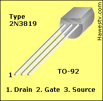
Gate and Source transposed to a J111, must be crossed over without shorting.
#2117
The Newcomer's Forum / Re: First Guitar Amp Build
May 27, 2012, 12:14:44 AM
Awww, come on Phil, that's only a bit of bird poo; a good dust and a bit of a wash with some metho and it would be good as new (however it is a bit of a distraction from the main game here, but has already provided one salutary lesson about chassis heatsinking).

Not just Fender.  Lots of people who should have known better have fallen into this hole - see my Gibson G-20 repair story (and let's not mention Savage).

I'd say at a guess that the two missing power supply fuses imply that the output stage is boofed, but again that's just everyday bread and butter.

Calx - see;

http://www.ozvalveamps.org/solidstateamprepair.htm


Quote from: CalxIt does seem that a lot of the larger companies are as much if not more interested in cost and ease of manufacture than longevity.

Oh you got that dead right, but far from selling new stock to old customers they actually end up trashing their own reputation.

And wot Phil said about electrical safety and metalworking gunge.

just one of many such you should read and take to heart;

http://www.ozvalveamps.org/safety.htm
#2118
Quote from: J M Fahey
So I stick to my guns about having independently invented and applied mixed feedback technology in 1972.

No argument from me JM, quite a few things have been invented independently in more than one place, Calculus for example.   :cheesy:

Just to note that the RCA scheme I posted above is a bridge that actually allows the current feedback to be varied through zero to either phase.
#2119
Quote from: J M Fahey
I guess I invented "Valvestate" on my own, about 15 years earlier than Marshall, go figure.

No JM, you invented it on your own, but Marshall ripped it off.

Attached is from "High Fidelity Sound Reproduction", 1958, Newnes.  I tried this on a KT88 bass amp build in about 1968 but, not understanding that the Celestion 18 was already in a grossly overdamped cab, found it didn't make any difference.  I've only started to reconsider this idea since reading Rod Elliot's stuff and thinking about trying to make SS amps sound more valve-like.

It's cruel that nobody gets credit for nutting out something second, but I have no doubt at all that Jim Marshall would have been very well aware of the prior RCA work.
#2120
The Newcomer's Forum / Re: First Guitar Amp Build
May 26, 2012, 02:39:30 AM
Quote from: Calx
I think my brand will be "White Noise"

I like it.   :tu:

Wot Phil said about Class-A. +1

Except for anything below 30 watts only being suitable for land fill, I agree with Phil and Spud.

Personally I'm not all that taken with all-in-one chip amps and I couldn't see myself going that way for a guitar amp - HOWEVER - what Spud says is right.  Looking at it from a manufacturers point of view chip amps are a very attractive option when you consider how much messing about they save on a production line, and that's what we have to keep in mind here with this project.

Quote from: Calx
Calx> Does anyone know of where I can get a decent schematic of a power amp with the chip?

GIYF

I'm going to look in a minute, but it is normal with most IC's that the data sheet contains a representative circuit, and many manufacturers simply follow this; so do what I am about to do, go to;

http://www.alldatasheet.com/

...and download the .PDF data sheets for the LM3886, the TDA2030/50 and LM1875 chips that JM suggested, and have a good meditate on them. {you have to click to view, wait for it to come up locally in your PDF viewer, then name and save to your datasheets folder}.

Put that speaker in a plastic bag before it grows a fur overcoat from drill swarf.  Once a tiny bit of swarf finds its way inside to the pole gap you can just about chuck it as a hopeless cause; otherwise it might be useful.

Google the transformer manufacturer name and type number - you might get lucky and find its spec.  The voltage rating of the two big blue electros will give you a clue to the secondary voltage.

You will notice that Carlsbro have used the chassis as a heatsink for the output pair.  This is a clue as to why this amp is junk.  Using the chassis as a heatsink, particularly a steel chassis as this appears to be, is one "saving" too far, and a short path to amp history.

Real heatsinks are made from ali and have fins mounted vertically where air can freely circulate past them, and that doesn't mean boxed up inside the cab.  Guitar amps tend to get used on stage under hot lights and they need to be designed conservatively for heat flow.  Whatever the nominal output wattage, you are going to have to get rid of at least as much as waste heat, and on-stage ambient of 40 degrees C are not uncommon.

Notice that the more significant controls have larger knobs.

Yes, that is a spring reverb tank.  By all means save it for a project, but I council against trying to include reverb (or any Fx) in your design - you have enough on your plate already.

The Carlsbro sure is a filthy mess, but it looks complete to me and this is the sort of thing I refurbish and bring back to life, so I wouldn't wreck it.  It may be useful to provide power generally, and a preamp for testing your mains amp, a main amp for testing your pre - maybe.  The thing is, clean it up and have a look at how a manufacturer has created an amp similar to your intent.
#2121
The Newcomer's Forum / Re: First Guitar Amp Build
May 24, 2012, 03:06:06 PM
A Google search turns up three different Carlbro Colt 45's; L/ead, B/ass, and K/eyboard.  I'll bet there are only minor differences.

Since this amp is rated for quite a bit more power then you intend there are likely to be various useful bits for prototyping, not least the power supply (which may actually be a bit too high in voltage for your needs).  A pic or two of the chassis insides would be helpful.

As for your preamp power supply, it is normal to derive that from the main amp supply via a regulator of some sort, often a simple zener diode.

You should be developing a list of preamp and main amp options to explore, and gathering datasheets of suitable chip amps and IC's used in your options (e.g. TL07x series op-amps), the TDA2030/50 and LM1875 chip amps suggested by JM, get catalogs from Farnell, RS Components &c, and have a look at what is available in the way of power transformers, bigish electrolytic caps, and hardware such as jack sockets, and dress stuff like knobs and case corners.

You should be developing your first conceptual drawings of what it might generally look like externally and internally, and how the various parts might go together.

I still sketch a lot using pencil and paper, but I also have a favorite drafting programme, an old thing called EasyTrax which is professional abandonware and free, originally intended as a PCB layout programme which it still does well, and also useful for more general drawing.  But everyone has their own taste and some people think highly of Eagle (for example).  I don't, but whatever floats your boat and gets you results.  If you are going to get a PCB done you need to identify your local suppliers and find out what format they like artwork to be submitted in, and be influenced by that.  Ditto for any metalwork, panel designs, and so on.

#2122
Fresh dry metho a.k.a. methanol, also known as methyl alcohol;
or ethanol, a.k.a. ethyl alcohol, pure alcohol, alcohol absolute;
or isopropyl alcohol a.k.a. isopropanol, propan-2-ol, 2-propanol, rubbing alcohol.

But use fresh stuff 'coz they are hydroscopic.
#2123
I've corrected the tempco in my original post.

The suggested minimum span of 200mV relates specifically to clean switching of the LED elements as a bar graph.  In this application the indication is secondary to the fan control function and sometimes not even used, however in the ones I've built, and the current mirror version shown in J.C.Maillet's video, this isn't actually an issue and simply appears as a bit of glimmer as each LED comes on, rather than a neat clean switch; it's cosmetic rather than functional.

I mention in several places that the LED outputs of the LM3914 are programmable current sinks.  The current per step is set at ten times the current drawn from the reference output.

The power dissipation in the IC would be due to the total current multiplied by the drop across each output current controller, not the total current by the supply voltage - you are calculating the power in the load, not the IC.

Because the IC outputs are current sinks the maximum current is determined by the IC, not by the fan rating, and the IC is operating within datasheet specs.

In all the builds so far the IC is also in the area being cooled by the fan, so this tends to be self-regulating anyway.

If indication LED's are included then yes, they will drop somewhere in the region of 2-3 volts, however electrically commutated brushless fan drives do not have the same voltage/speed characteristic as a conventional DC motor which tend to have a  pretty linear voltage/speed relationship.

Brushless fans have a more "S"-curve relationship in that they don't even start turning until they get a few volts across them, then the speed ramps up fairly steeply against voltage and they are running at close to full speed by the time they get to about 10 volts, the remaining couple of volts making little difference in revs, and even less in cooling effect.

Experiments I conducted back in the days of mains powered 5-inch fans and 10-inch floppy drives showed that the rule of thumb is that a fan produces about 90% of it's cooling effect in the first 10% of its rev range (or call it 80/20 if you like), allowing considerable slowing and quietening with only slight loss of cooling.  In those days I simply added a small capacitive dropper in series with the fan to take it down to about 30% revs, and experienced no overheating as a result.

Most fans are way overkill because it only requires a slight draft to remove the hot air layer against the surface of a heatsink, and that's where most of the cooling effect derives.

In free air the temperature of the air layer at the surface of the heatsink may be somewhere around 20 to 50 degrees hotter than ambient to drive convection, but once you replace it with air from a fan it makes very little difference if the layer is now 5 degrees or 3 degrees hotter than ambient because the limiting factor is the transfer of heat from the heatsink to the air, not the removal of air so heated.

This is why a semiconductor will still cook on an undersized heatsink even in in a howling gale.  Thermal circuits are still circuits, and changing the ground resistance from 5 milliohms to 3 milliohms won't help if there is still 5 ohms of resistance elsewhere in the circuit.
#2124
The Newcomer's Forum / Re: First Guitar Amp Build
May 23, 2012, 05:25:33 PM
I am a retired electronics tech and spent a large slice of my life designing, building and servicing industrial and bio-med electronics.  I've also moonlighted as a muso (keys and guitar) and music/theater tech/soundie/lighting operator since I was a teenager.

Free circuit modeling/drafting software?  Sure, Google LTSpice. There is also a strong Yahoo users group.  A word of caution about circuit modeling - the ultimate model is a hardware prototype; it automatically includes all the stray resistances and coupling capacitances that cause trouble.

I have no experience of it, but I've been looking at the LM3886 chip amp which seems to already have a lot of community support for guitar amp applications, builds to look at, people's problems to learn from, printed circuit layouts to be informed by.  It's quite a bit more powerful than your intended 20 watts, but when it comes to guitar amps it's wise to have some reserve up your sleeve (particularly heatsinking).

The guitar teacher is a double hit because the old amp provides you with a testbed and some bits, and your guitar teacher being experience in electronics and locally accessible to actually look at your problems (and you will have problems) is very valuable indeed.

What is the model number/name of the Carlsbro amp?

The circuit I attached is from Rod Elliot's excellent ESP site and you will find a related guitar preamp there that is well worth a close look;

http://sound.westhost.com/project27.htm

Like the one I posted from Rod's project 27, project 10 requires a preamp.  There is a good reason why guitar amps of the 20 watt class aren't Class-A, and that this one is for the audiophiles.

It is fairly normal that the master volume control is at the point of transition between the preamp and the main or power amp, and that the signal voltage level at this point is typically around 1 volt, or "line level".

This means (generally) that pre and main amps can be fairly easily mix-and-matched.  Take a look back at one of the circuits I linked to above and you will see a simple preamp that uses a couple of FET's and very simple top-cut "tonestack".  If you go for a dig on the net you will be spoiled for choice, but Rod's Project 27 preamp would be hard to beat.

I see JM has mentioned some other chip main amps which you should investigate.  As part of your project you should note the different IC's and circuits that you investigate, and why you decided for/against them.

There is no reason why you couldn't go with a transistor preamp, but these days even a fairly "ordinary" op-amp such as the TL07x is pretty damn good and easy to use, and you can go up-market to pin compatible things such as the LM833 which is still almost free to buy and close to perfect, or there are other "ultra" specialist audio op-amps which are not quite free and so perfect they make your eyes water (but are a bit of overkill amplifying guitar which has a typical output level in the hundreds of millivolts, not microvolts, coming via a thrash-metal stomp box  :lmao:).
#2125
Why wreck it?  If you don't want it give it to somebody who can be bothered restoring it.  As for "parts" - it's 50 years old and there isn't anything in there that you can't buy better new, and a lot that is simply useless once it is pulled apart.

Why don't you have a go at tracing the circuit?  A bit like servicing an unknown stereo amp you seem to have two similar preamp boards to compare, and two similar output stages as well.  Tracing one of the preamps should give you most of the other one, and ditto for the two output stages (which are likely to be identical).

If you are going to be doing any work on this I'd apply some heatshrink to the mains socket inside to avoid accidentally "shaking hands with beef"; and the "ground" switch certainly needs cleaning up (if you haven't done so already).

It appears to have two power trannies, one for the low voltage to supply the preamps and driver, and the bigger one to power the output stages.

The small tranny down between the heatsinks suggests that this uses an old style transformer-coupled driver.  I'll attach a circuit of an amp that I think used a similar driver/output stage arrangement to give you the idea.

I'm guessing that the board mounted vertically in the middle will combine the two input channels and feed the driver; that transistor mounted on the back plate will be a class-A driver for the output stages; and the missing fuse holder may go some way to explaining why one channel isn't working.

It's going to need a few new electros, but frankly I think this would be a poor choice of metalwork for a valve/tube build.
#2126
Amplifier Discussion / Re: crackling SWR bass amp
May 21, 2012, 11:41:35 PM
Quote from: Axtman
The strange thing is that I can hear the crackle when ALL the controls are turned down!  Of course it gets louder when the controls are turned up!

Well this suggests that it's in the power amp section or the power supply, and getting louder when the volume is turned up suggest it may be in the power supply.

I had no trouble finding a circuit (attached) but I can only find a copper-side pic of the board, however it looks to me like the main power supply filter caps are mounted on this PCB.  A fairly common fault due to the large mass of these components is fracturing the PCB trace and/or solder joint where they are soldered to the board.

It is almost certainly going to be a fractured track or solder joint, and highly unlikely to be a transistor itself - this is not how they commonly fail.

As JM says, it's a patience job requiring more of the same.  I've found that a single chopstick tapped on the board gives about the right level of impact to isolate these sorts of troubles.

Good luck, and let's know what you find.

{Enzo just beat me to it  :cheesy: }
#2127
The Newcomer's Forum / Re: First Guitar Amp Build
May 21, 2012, 11:04:42 PM
JM - I posted part of the course requirements that Calx is doing because it's actually a bit daunting.  This is somewhat up-market on a Science Fair project and more like the sort of project that engineering students at uni or senior college have to turn in.

What is being asked of Calx is not just to create a going guitar amp (he already has one of those) but to demonstrate that he understands how to engineer a product for manufacture, something I'm sure you will agree is of a rather different order.

He's not going to put his design into production, but he has to go through the motions and produce a design package that could potentially be then taken to cabinet makers, metalwork shops, and PCB suppliers.  I say "daunting" because I have been through this process many times and it always looks easier than it actually is - as you say "tweeking", or even getting serious bugs out, can take years.

{A company building a prison in my home state of Victoria just went broke, partly because the windows and doors they ordered from China were the wrong size, and as somebody said, having doors that fit seems pretty basic to a prison.}

Given that he has a deadline in about six months it is going to need a heavy application of the KISS principle just to get there.  {Calx; "KISS" stands for "Keep It Simple - Stupid", take the line of least resistance and don't get adventurous, pick the simple and obvious for each step, e.g. no in-built fuzz box.}


Calx; I notice that your course syllabus places some stress on drawing and sketching.  I can't tell you how important I think this is.  You are going to need to produce drawings of your cabinet, chassis, and PCB layout, and before you get to the final stage there may be quite a bit of horse-trading, e.g. you can't get the transformer or heatsink you wanted and what you can get is a different shape with different mounting holes.  So expect to produce several versions of each, and here "version control" becomes vital; all drawings should have a title block showing all the normal guff, but some sort of version number is vital, particularly if you are going to be discussing drawings with people on-line, to make sure that we are literally all on the same page.

I use a date group for this function, so today is 120522 and if there is more than one drawing a day (we hope) a 24-hour time group as well, and since we are all in very different time zones you need to specify GMT/CUT because you are on GMT, I am some 10 hours ahead, and I'm guessing that JM for example is some hours behind.  So 120522-1203GMT should be a serial number that leaves no doubt which is the latest revision.

The honest designer will tell you that there is very little that is new under the Sun, and that most of us (very quietly) operate on the motto "plagiarise and hybridise".  In this particular project you don't have to worry about being sued for copyright, and imitation is not only the sincerest form of flattery, it is also building on the valuable experience of others.

So generally I'd take the Marshall Lead 20 as an "inspiration", since it represents exactly your aim having gone through exactly the process of preparation for manufacture you are supposed to put your design through.

Most commercial small amp designs are crippled at birth by being ... well ... small.  At the 10-20 watt power level I'd suggest that you consider using a 12-inch speaker and allowing for a sealed enclosure of at least 50 litres (that's about root(2) cubic foot); you imitate the simple U-shaped chassis with front, back and floor ('tho you may want to use separate front and back panel sections to allow finish such as anodizing, painting, silk-screen printing of control legends, and so on), and the floor might need tabs at each end to secure the chassis.

You don't want it to look too much like a clone of a Marshall either, so I'd be inclined to make it a bit narrower and taller, but your cab size should be driven by what sizes of timber are locally available that minimise cutting and working.  Here again your will find you produce a lot of sketches and drawings of different arrangements until you find one that satisfies the largest number of conditions.

It will also not be hard to improve on the Marshall heatsinking arrangements and use a rear-mounted heatsink that can actually get rid of some heat.

I normally build my amps out of individual components, like this Marshall, but in your case I think you should give serious consideration to using an integrated chip amp where you can pretty well use the circuit off the data sheet, bolt it to the heatsink, and worry about other things - such as the preamp.

An important point to keep in mind with any amp build is to keep the mains wiring well away from all the other wiring.  This is mainly for safety considerations, partly to stop main-carried electrical noise getting in to your amp circuits, and partly because such segregation is required for type approval in just about every potential market; and consideration of such legal pitfalls should be one of the critical things your instructors should be looking for in your design.


I am willing to provide whatever assistance I can, but ultimately it is down to you to understand your course requirements and fulfill them.  Six months may seem like a long time now but you will be horribly surprised how quickly it will evaporate.  Murphy's Law states that things always take longer and cost more than expected (doubly true for software projects), so getting in early leaves you with some "lead time" up your sleeve when something goes wrong - and it will.  I look forward to you posting your initial design ideas.
#2128
The Newcomer's Forum / Re: First Guitar Amp Build
May 20, 2012, 01:48:55 PM
Quote from: Calx
I would like to build an amplifier for my A2 level Product design project, maybe a 10 or 20 watt amp.

Being on the other side of the planet I first had to do a bit of research to understand what "A2 level Product design" is, and after wandering around the AQA site (where they never did get around to explaining what "AQA" stands for) I gather that this is a module in the English General Certificate of Education Advanced Levels, what some would call Matriculation, the end of Secondary schooling with possible university entrance next.

Quote from: AQA
---
Summary

This specification is designed to encourage candidates to:

    develop a broad view of design and technology
    develop their capacity to design and make products
    appreciate the complex relations between design, materials, manufacture and marketing.

AS outline

At AS level candidates develop an understanding of a broad range of materials, with emphasis on the life cycle of products, manufacture and final disposal. This specification also considers the broader issues for the designer including the environmental sustainability of products and consumer safety:

    Unit 1: (PROD1) Materials, Components and Application
    Unit 2: (PROD2) Learning Through Designing and Making.

A2 outline

At A2, the specification offers candidates the opportunity to further develop the knowledge and practical skills from AS. Candidates will continue to develop a body of coursework alongside an understanding of the processes and procedures of commercial production and manufacture:

    Unit 3: (PROD3) Design and Manufacture
    Unit 4: (PROD4) Design and Making Practice.
---

As it happens I had a lifetime in the design, manufacture and service of industrial electronics while moonlighting as a musician and music/theater tech building and repairing guitar amps and sundry showbiz-related gear.

If you haven't already an early task is to go out and see what is already available as a "10 or 20 watt" guitar amp.  Call this basic market research, checking out what such a product looks like, what potential customers and users expect.

I started by Googling "10 to 20 watt guitar amplifier" and having a look at the images that brought up.

The first thing to notice is that this got 1.6 million hits including some very heavyweight names such as Fender, Behringer, Ashton and many lesser knowns, at prices ranging from $50 to $1500.  So the first message here is that while this is an interesting design project, and you should end up with a guitar amp out of it, you can forget about getting rich quick by taking the industry by storm - there are many thousands out there ahead of you.

If you are going to build any guitar amplifier some of the things that you must consider include;

- features and facilities
  - inputs and outputs (how many? what levels/connectors? headphones?
  - effects
  - controls
  - speaker size
- the box or case it is going to go in (head and cab or combo?)
- the chassis metalwork to hold the amp electronics and front panel
- the printed circuit board (for ease of manufacture, and rework/repair)
- discreet components or IC's?
- heatsinks and cooling
- power supply, power mains safety (and approvals in different markets CE, C-tick, UL ...)
- ease of assembly
- ease of disassembly and repair
- finish, styling, dress
- costs, "price point"

...and lots of associated details besides.  Many of the above are inter-active meaning that the process of design can have a lot of circularity and backtracking as various factors are traded off against each other during product development.

One particular amp stood out, the Marshall Lead 20, simply because I could find the circuit, and external and internal pix that help illustrate the reality of the design process.

Quote from: marketing
---
Vintage Marshall Lead 20 (Model 5002) 20-Watt 1x10 Guitar Amp in Excellent Condition, made in England, serial number U41410. Features a 10" Celestion G10L-35 speaker. The Marshall Lead 20 is 17" tall, 18 1/2" wide, 9 1/2" deep, and weighs about 28 pounds.
Buy the Marshall Lead 20 Model 5002 Guitar Amp 1x10" Celestion for 199.00!
---

The external and internal views of this amp are attached below.

Here are some different takes on the same idea (not related to each other);


Jade Hot Shot


ESP


Marshall Lead 20 circuit


Some things to think about.
#2129
I've been having a close look at this circuit and there are more than a few curious features that deserve comment.

I have redrafted it so that it has component designators for identification.

Starting at the input, a minor point; it is more conventional to place the grid leak (R1) after the grid RF stopper (R2) than before it, as here.  Unlike in an output stage where the function of a grid stopper is to prevent self-oscillation, in preamp stages the grid stopper is to prevent external Radio Frequencies entering the amplifier, and is therefore normally placed as close as possible to the input socket.

What initially grabbed my attention when glancing at this circuit is the value of R3, the first stage cathode resistor, in conjunction with the value of the anode resistor R4.  The Mullard databook give typical operating conditions for valves such as the 12AX7, and for around 300 volts HT with a 220k anode load (R4) the value for the cathode resistor R3 should be 3k9.  The operating current of this stage is around 0.6mA and the effect of such a low value for R3 is to reduce headroom and increase stage distortion.

The cathode bypass, C1, has been set to a fairly low value meaning that the stage has about a 4dB rise from 100Hz to 1kHz, clearly aimed at tenor guitar.

There are a number of components that seem to have no useful function, and R5 is the first we encounter.  Since there is already a DC path from C2 to ground via R6 and gain control U5, which are also of much lower value, there seems to be no point including R5.

The gain control circuit, R6, C3, U5, seems to be at odds with itself.  The effect of R6 & C3 is to provide some fixed treble boost, however this is minor and doesn't come into effect until about the fourth or fifth octave above Middle-C.  It would be more normal to omit R6 altogether and take C3 to the wiper of the gain pot, then becoming a more conventional "top coupling" cap.

Again we seem to have a component, R7, which has no function and can be omitted.

Given that some top boost has been applied via C3 the inclusion of R8 more than throws it all away again.  The object or function of R8 is obscure, but its effect is to act as an ill-defined top-cut filter in conjunction with the Miller capacitance of the following valve, U2.

An important aspect of circuit design is to try and make the circuit as insensitive as possible to the aging of components, and to replacements during repair.  The main effect of R8 is to make this stage more sensitive to changes in the Miller capacitance of U2, and to different Miller capacitance of any replacement valves inserted at that position.  Similarly R8 is large enough to add bias due to grid leakage and thus make the actual DC operating point of U2 less predictable.  It is also worth mentioning that because the grid leakage current can flow through the wiper of the Gain control it will tend to make this scratchy in operation, through no fault of its own, and which no amount of cleaning will cure.

The value of cathode resistor R9 is spot-on for its anode load (R10) of 100k.  Again the low value of the cathode bypass (C4) shapes the low frequency response of this stage towards tenor guitar.

Having obtained around x60 gain from U1 and x55 from U2 (~x3300) we now encounter R11 and 12 which form a fixed attenuator of x0.6, reducing the effective gain at this point to 3300*0.6=1980 or about x2000.  The reason for doing this is not at all clear.

Again we encounter a grid series resistor, R14, which has a much lesser effect than R8, similarly seems to only make this stage less predictable and more sensitive to device variation in U3.

More predictable is the effect of C6 across the anode load of U3 (R15).  This provides a heavy roll off above about 1kHz, negating the effect of C3.

I would personally reserve the title "Ultra gain" for a preamp where all the stage anode loads were constant current sources, thus making them Maximum Available Gain or MAG stages, but in stages U3 and 4 we see that the cathode bypass resistors aren't bypassed, meaning the application of local negative feedback and quite a bit less than MAG from each stage.

Similarly R17 at 470k provides less stage gain than by using a 1Meg.

Again we have a large value grid series resistor in R18 which has a similar effect to R8 discussed above.  By the time we get to the entry to the tonestack at C8 we have about 120dB of available gain, but we also have a pretty savage overall roll off above about 1kHz.

And again in C8 and R21 we seem to have two components that serve no useful function.  Both could be omitted (as they are in many similar amplifiers) and the anode of U4 taken straight into the tonestack since the DC path is already blocked by C9, 10 and 11.

Phil has already touched on having the unbuffered output of a High-Z tonestack subject to following loads, and with this particular Marshall configuration nothing less than about 1 megohm load will produce acceptable performance.  The use of loads as low as 47k, particularly at high setting of the volume control U9 will result in savage tilting of the response downwards into the bass from about 1kHz.

By re-positioning the tonestack between U3 and U4 it could be fed either conventionally from the anode of U3, with R16 bypassed to provide high gain (or perhaps from U3 as a cathode follower), and U4 could certainly be used as a cathode follower output buffer which would make the tonestack totally indifferent to output loading.

Taken overall this is a preamp that isn't sure of what it really wants, with contradictory and ill-defined response shaping, gain mixed with attenuation, and the use of stages (particularly U3 and 4) which aren't employed to best effect. 
#2130
The soldering on the input sockets looks none to brilliant.

If you plug a pair of headphones into the headphone socket is it still weak, or do you get a good level in the 'phones?