Menu

Show posts

This section allows you to view all posts made by this member. Note that you can only see posts made in areas you currently have access to.

Show posts Menu

Messages - Roly

#2071
Thanks Tony, that's much more like it and helps a lot.

Paolo, take a look at your (excellent, crisp, and well lit) pic 874 - a bit below the middle there are a pair of red-ish resistors connected to the yellow wires to the output pair, and marked "0.5 ohm".

These are a dead giveaway as R10 and R11 (Rod's cct above) and when you are dealing with an unknown amp you look for something like these to help orient yourself.

Another thing you look for is if the type numbers on the output transistors are the same (quasi-comp, generally both NPN as here), or different but perhaps by only one number (fully comp NPN/PNP pair, e.g. BD139/BD140, 2N2955/2N3055).

That would make the two blue wires just to the right the output transistor base connections (between the two 150 ohms brown/green/brown/gold, like R8 and R9), and the two transistors to the right will be the drivers (like Q3 and Q5 above).

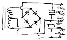
A couple of variations; your amp appears to use a split rail supply and direct speaker connection rather than a single rail and output coupling cap (C5), so the supply will have a grounded mid-point between the two caps at left, just above the four diodes for the power supply bridge rectifier.


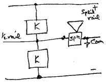
The transistor just above the centre of the pic will be doing the same anti-crossover bias and thermal compensation job as diodes D1, 2 and 3, and the transistor just to the right of that will be the VAS - Voltage Amplification Stage, Q2 above.

I'm guessing, but I'd say that the two transistors on the right-hand edge are a differential "long-tailed pair" doing a somewhat better job of the task of Q1.


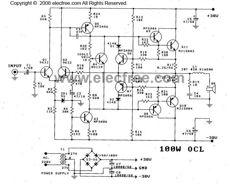
Here Q1 & 2 are the long-tailed differential pair, Q4 is doing the bias/thermal comp, and in this circuit Q6 & 7 are providing overload current limiting protection (generally not used in combos where the speaker is permanently connected and not externally accessible).

It's a bit of guesswork, but it looks like your amp uses a transistor bias rather than the string of diodes, but yours doesn't appear to be adjustable, which means that it will be fairly conservatively set, and could well be the source of your "ghost fuzz" - crossover distortion.  Tell me, is it worse at quieter levels than louder?

(http://www.ozvalveamps.org/repairs/solidstateamprepair.htm)

{Here endeth the guided tour of your output stage - postcards and tourist geegaws are on sale on the other side of this post.}
#2072
The Newcomer's Forum / Re: Building a bass amp?
June 20, 2012, 08:07:52 AM
Interesting @STDog, didn't know that.  I actually used to roadie a double bass player, but sousaphones are pretty thin on the ground in Australia, the occasional Trad Jazz band, never mind in massed swarms (or whatever the collective is for sousaphones).  Do people still go to orchestral performances any more?  I was sorta thinking of massed German basses when I wrote that, but I thought that most readers wouldn't know what I was talking about.  In my misspent youth I used to go around playing pipe organs and 32 foot Diapasons spoil you for real bass.

@mexicanyella - yes, that's right, the upper frequencies are radiated from the front of the speaker cone, and the rear is loaded by the J-horn.

No; what happens is that the radiation crosses over. Down to the acoustic crossover all the radiation comes from the front of the speaker because the inertia of the mass of air in the horn makes it effectively a sealed box, but as the efficiency of the front radiation starts to drop off so the air mass behind (by arrangement) starts to respond and as the frequency comes down the whole cab acts like a horn, with little radiation from the front of the speaker cone.

It is effectively a combination of both a mid frequency direct radiator and a low frequency horn. {The Siamese 'tho does have some internal vents and makes use of the radiation from them to augment its bass output, but then it's rather more complicated inside.}

Because the replaced fundamental is all in the mind you could actually call it wishful thinking.  ;)  I was talking to a techno mate about this topic who pointed out that MP3 encoding makes heavy use of this subjective effect.

This stuff goes some way to explaining why chord inversions, 'tho nominally the same, actually sound a bit different.
#2073
Nah, something isn't right there; the TD526 comes up as a half watt transistor in a small D-package, and that certainly isn't what you've got there.

Not sure what you mean by...

Quote from: Paolo
I'm assuming the input to the heatsink is on the left (viewing from amp front) and the output on the right.

These two transistors act as a "push-pull" pair, one driving the speaker during the positive half of each signal wave, and the other during the negative.

The output stage of your amp will look something like this (with thanks to Rod Elliot)...


At rest the join of R10, 11, and C5 is at about half the overall supply voltage (35/70V), therefore this is called the "half rail", and it's also the output node.

The output pair are Q4 and Q6 (the ones bolted to the heatsink).  When the input swings positive transistors Q1, 2, 3 and 4 all turn on, causing the output via C5 to swing positive and drive the speaker cone in one direction.

Similarly when the input swings negative the transistors above turn off and Q5 and 6 turn on pulling the output negative and driving the speaker cone in the other direction from its rest position.

There are several different ways output stages can be arranged, but this would be one of the most common.


The white gunk is thermally conductive gunk intended to fill the small voids between the nominally flat surfaces and improve heat transfer.  Once  it's in place drying out doesn't matter much since the solids are what do the thermal conducting, it's only a paste form so it's nicely conformal when it goes on.

When you remove a device however if the paste has dried out you need to clean of the old residue and apply a dob of fresh.  Any place that sells power transistors should also sell mounting kits, variously shaped insulators, and stepped insulating washers for the mounting bolts.

This stuff was particularly necessary with mica washer insulators, but there are now grey floppy rubbery insulators that are conformal and thermally conductive and don't actually require the white goo.

(PS) Joe mentions silicon grease thermal coupling compounds, and there are several different types.  The older silicon grease was a milky paste and not sticky at all, but the while gunk that I get, "Unick", is like artist's white paint and sticks to everything, and it sounds like Joe uses something else again that is rather more friendly.

Remounting the output transistors with fresh goo certainly won't hurt, but be careful of the insulating wafers and washers, the mica wafers are fragile and it all must go back so the tab of the transistor is isolated from the heatsink (test with ohmmeter after remounting).

Quote from: Paolo
Thanks for the explanations and further advice. You have a real knack for explaining things in a way that i can understand!

My pleasure.  I have been doing this stuff since the days of valves (tubes) and for much of that time I have had trainees.  When it comes to electronics it's us imperfect humans against Murphy and the very picky universe, so I do like a win, and the moreso when I've helped an "improver" to a win and a better understanding.  And you can always award chip points, top left.  ;)

Far too many musicians are far too often victims of their gear.  Rock 'n Roll has always been somewhat technical with amps 'n all, so really the modern guitarist needs to also know enough about electronics to survive.
#2074
The joys of grandparenting - you can hand them back!  ;)

The little Vox box looks fine as a pre, but you can prove the point by getting a suitable patch lead and patching its output into the Aux input of any stereo.
#2075
The Newcomer's Forum / Re: Building a bass amp?
June 18, 2012, 08:57:26 PM
Oh, drummers, yeah, I forgot about them (easy to do).

Still, I rather like the idea of a guitar amp with minimalist controls...


Yeah Joe, looks like you could turn that into a bridge with little trouble.:tu:   Where did you score the chassis metalwork?
#2076
The Newcomer's Forum / Re: Building a bass amp?
June 18, 2012, 01:58:23 PM
Nope, looks about right to me (as long as it also has a fan somewhere out of sight)  :lmao:
#2077
Well, apart from playing around with the resistor value in the preamp you can also play around with the value of the capacitor.  For large values the gain control will effect all frequencies equally, but as you reduce its value the gain will tend to be tilted towards higher frequencies.

As the original cap was 10uF you could try some larger values and this might make the bass end more responsive to the gain control (and maybe not, maybe it is already large enough) but you can certainly try some lower values such as 1uF, 0.1uF and 0.01uF.

The smaller values will be non-polarised types, such as "greencaps", that can be put in either way.  These will confine the effect of the gain control to higher and higher frequencies.


My failure to mention your "ghost overdrive" was deliberate.  Where ever possible in electronics you try to deal with only one thing at a time, or things can very rapidly get confusing.  Now that you seem to have the preamp under control to your satisfaction we can move on to the next problem.

I suspect that what you are calling your "ghost overdrive" is actually some distortion arising later in the amplifier, and my guess would be in the output stage.

You will notice that there are two output transistors.  What happens is that the signal is split into the top half and the bottom half, and each transistor amplifies its half, either the positive half or the negative half.  Since the signal consists of waves that swing back and forth between positive and negative so each of the transistors take turns to amplify the output.

Now ideally when one stops, the other should take over seamlessly, however that isn't always the case and you can have a tiny pause in between.  Since the signal is crossing over from one to the other this sort of distortion is called "crossover distortion" and happens to be a rather nasty sounding form of distortion even at very low levels.

To overcome this, or at least minimise it, the two output transistors are biased so that they are both slightly on or conducting when at rest, so that when driven one starts to conduct a bit before the other stops (somewhat like the next runner in a relay race starts running a bit before the hand-over).

In inexpensive amps (and even some expensive ones) it is easier to leave a bit of crossover distortion rather than put in the components to set the bias correctly, and to hold it correct for changing temperature.

Lacking a circuit it is hard to say, but I suspect that this is the cause of your "ghost overdrive".

If you follow the wires from the transistors on the heatsink back to the board, it could be helpful to have a photograph of this area of the board where they go.

Also, the transistors on the heatsink will have type numbers such as 2Nnnnn or 2SAnnnn, 2SBnnnn, 2SCnnnn, or perhaps just A, B, or C followed by some numbers - these would be handy to know since they will give a hint to the circuit being used.

HTH = Hope This Helps.
#2078
The Newcomer's Forum / Re: Building a bass amp?
June 18, 2012, 12:41:57 PM
Quote from: J M Fahey
As you see, I take them everywhere (if possible), to see what "Dad's work" is about.

I think that's brilliant JM; they will grow up with some great memories,  and understanding how shows are put together, all the background work required.  :dbtu:

After my son was born I often had to combine work with child minding, so I would take him on jobs such as office computer repairs and mixing gigs wherever possible, but I would also take him to visit nearby small factories and ask to show him around, so he got to see glass works, sheet metal, various textiles, and an iron foundry that was a favorite - and never got knocked back once.

Quote from: J M Fahey
and they have no volume pots !!!

But what is "volumen"?  Are we evolving to a guitar amp that just has a switch marked "off" and "11"?   :cheesy:  Nice looking gear.

Quote from: mexicanyella
a clean, uncompressed and fairly bright tone

I agree with JM, a fairly basic amp of 50/60 or 100 watts, and I would suggest the AES rear-loaded J-horn with a suitable 15 inch speaker will cover both a rich bottom end and still allow brights from the front, and be practically portable.

I would either build your amp as two units, preamp and main amp, or at least include Fx send and return.  Even if you don't intend to include Fx this is still the place you can experiment with external graphic or parametric EQ's and such.

Apart from cost I see two important advantages in building your own gear; satisfaction that "my" rig really is my creation; and when it needs repair (as they all do at some time), or you feel you want to modify it in some way, you are fully in charge, you know exactly what is inside the boxes and the compromises are all yours to own or to change.

Rod's amp designs are as good as you will find anywhere, but two important points, don't skimp on the power supply, or the heatsink - it is hard to have too much heatsink in a gigging amp (and you always seem to need more than you initially think).
#2079
The Newcomer's Forum / Re: Building a bass amp?
June 17, 2012, 07:25:17 AM
Well, to be frank @mexicanyella, I consider any speaker for any use in a 1 foot cube to be a practical joke.  The 15 that is in the Siamese came out of a commercial vented enclosure, intended for bass, that I came to call its "carry crate" 'coz as a speaker cab it was a bust, and as a bass cab doubly so.

Let me quote some actual numbers to hand.  A Dai-1Chi "instrumental" 10-inch (94dB/W, 400Wmax) has a free-air resonance Fo of 63Hz.  From a different table, a 10 with an Fo of 52Hz has a resonance of 105Hz in a 1 cu ft enclosure.

That's roughly the open-G or top string, leaving the rest of the bass guitar down a mineshaft (and that's before you scale it up 20% or so).

This is about the same size as the Roland Cube series, and I know from painful experience that they start to roll off about Middle-C, or 250Hz odd - and these get sold as "keyboard" amps cor blimy!  Computer keyboard maybe, 'cause they are totally bloody useless as synth amps - shreeking lead guitar is the only thing they are good for (and door stops).


(Counts up on fingers...) I make that 32 drivers and 1.2 (or 2.5) kilowatts for the backline bass alone.

I think I rest my case.   :-X

{should we ignore the mike in front of the bass bins and the rather large bins behind which I assume are only part of the on-stage foldback - what do the FoH bins look like JM?  :o  And we're not fooled by you using dwarfs to make the bins look bigger either.  :lmao: }

Of course all this depends on the playing style and desired effect.  If the bass player uses a popping and gar-dang style then the fundamental may be a lot less important.

But for those bass guitarists who;
- are not frustrated lead guitarists
- are not rich
- are not (yet) famous
- don't have a road crew that gets mistaken for a small invasion force
- don't play stages that are so high they need oxygen
- play venues where the majority of the audience are still in the same State, and
- want actual fundamental bass notes

...some compromise and cunning are required.  ;)
#2080
Well the particular speed stripping musician I'm thinking of was a drummer (and a very good one), but I think as such he can be forgiven for not recognising the danger of putting a new battery in his pocket after helping a guitarist with a troublesome stomp box.

Yeah, you stomp on a lithium battery and the phrase "incendiary device" comes to mind.  :o

Thing is, if the amp in question didn't use transformer coupling and was just a comp or quasi-comp there doesn't seem to be a lot of point trying to clone it when there are so many chip amps available these days.
#2081
The Newcomer's Forum / Re: Building a bass amp?
June 17, 2012, 12:46:30 AM
My pleasure, because it has long been a special interest to me as a key player and soundie/mixer.

We are all boiled frogs.  About the only time you actually hear real fundamental bass these days is at big arena rock shows with rows of W-bins the size of double beds along the front edge of the stage, and you can actually feel the kick drum in your chest - fooom!

My son is typical of the iPod and doof generation, and you should have seen his face the first time I played him some Toto through the Siamese.  "Never mind you don't like the naff music - listen to the bottom end".  Once you have the illusion explained, and actually experience real fundamental bass guitar bottom-E, sound systems never sound the same again.  ;)
#2082
Paolo, I've been working on guitar amps for fifty years odd and I can sadly assure you that amps that are poorly designed are far too commonplace.  Even very well known names like Marshall have amp models that are dogs to live down.

The fact that we have found no actual fault tells us that this amp is working as it was out of the factory.

"Gain" is just another word for "volume" and as I understand your posts this control has been changing the volume, just not as much as you would like.  "Overdrive" means enough gain to drive the amplifier into clipping or limiting with the attendant crunchy or grinding tone of distortion due to the amp being driven past its clean range.

This amp has two inputs, "normal" and "boost".  Well actually what it has is one input that cuts the input signal back a lot, "normal" and another that cuts it back a bit less, "boost".  These two signals are then taken to the same place, the input of the variable gain stage where the gain is set by the gain control.

Why did I suspect the electrolytic?

A couple of reasons, firstly that these types of caps "dry out" over time and lose capacitance which would, secondly, be consistent with a remark you made that suggested that the gain control was acting like a middle/treble control.

This could be simply subjective, or it could be caused by a cap in that position that wasn't fully open circuit but had only lost a lot of it capacitance, so I got you to test it by substitution.

Since this produced no change we could then assume it was okay, and move on to modding the circuit to get more gain from the first stage, i.e. by reducing the resistor that sets the upper gain limit on the gain pot.  When you put in the wire link you experienced how high the gain could go.

As I said above, once the gain got high enough some stage down the chain ran out of headroom and started clipping, giving you "overdrive" gunge.  As it happens (and this is very common with solid-state amps) this clipping didn't sound too nice, and may give us a clue as to why the manufacturer selected a resistor value in series with the gain control that prevented you getting into this gain territory.


The resistance ranges, like the other ranges on your meter, define the highest reading on that range, so "200" is for measuring resistance up to 200 ohms, "2000" to 2k, and 20k, 200k and 2meg, ditto.  It is particularly important with these last three higher ranges where you have to be careful about your fingers - just try measuring your own resistance between your hands and you should see why - you are in parallel with what you are measuring, and you ain't no insulator.  ;)

Just another point about resistance measurement is that they must be made on circuits that are dead - voltage free - or you will a) get incorrect readings, or b) blow up your meter.  All of these style of meters are also quite prone to dirty connection on the range switch, so if you get readings that don't make sense, just try wiggling the range switch a little bit.

A resistor with all blue stripes would be 660megohms.  Google "resistor colour code" and learn how to work out the value of resistors from their colour bands.


...and...

http://www.michaels-electronics-lessons.com/resistor-color-code.html

Phil has been paying much more attention to your reverb problem than I have, so I would trust his advice/opinion.

HTH
#2083
Gel cells are just a different form of lead-acid.  All batteries must be treated with respect because they store energy, sometimes quite a lot of it, and when something goes wrong (like a short) it can all come back in a rush.

I've seen a musician dancing around ripping his jeans off because the 9 volt stomp battery in his pocket got shorted by some change.  :o

But I can tell you that anything with lithium in it is a much scarier battery than any lead-acid.  Look at any of the lithium battery vids on Utoob.  :(
#2084
Tastefully chosen resistive dropper in series.  Catch diode is good, snubber is better.  Catch diode AND snubber is best.  The snubber is a resistor and capacitor in series, across the relay coil in parallel with the catch diode.

General rule of thumb, a resistor equal to the coil resistance and a cap in series from about 0.1uF for a low current relay coil up to 0.47uF for a heavy coil.  Snub the coil, no "pop".

The problem with just a diode is, particularly if there is any logic nearby, that the diode switch-on time is finite enough to flip flops and the like, and the snubber stops that little spike (been there, been done over by that; a spike a couple of uSecs wide by 3kV high; this is how car ignition systems work you know  8| ).  You don't need a zener for a relay supply. Just one more thing to fail.
#2085
The Newcomer's Forum / Re: Building a bass amp?
June 16, 2012, 06:14:32 AM
Well you can put a horn on anything, or anything in a horn, but horn or not there are a few physical realities that must be recognised and paid due homage.

Big speakers are used because they pump more air for a given cone throw.  They are also used because they normally will have lower mechanical self resonance frequencies, and once you come below the driver resonance the output starts to drop like a rock.

From my discussions with bass players it seems that groups of 10's are favored for two reasons, one is that some players like the more trebly "ga-dang", but it also seems that many bass players are willing to compromise on real fundamental "ommph" for the sake of portability.  I remember one discussion that ended on me asking if they were a bass player first, or a driver first, and if they were a bass player first then maybe they needed a bigger vehicle.

As a keyboard/synth player I have a foot in this camp because I want real bass from my left hand, and smaller speakers simply don't cut it.

There is a thing that all small speakers such as "bookshelf" and computer speakers depend on, and it's called the "replaced fundamental".

If you present the human ear with a group of third harmonics it is possible to fool the brain into thinking that it is hearing not harmonics but the fundamental note, even though there may be no fundamental there at all.

If you do a sinewave sweep (no harmonics) of typical computer speakers you won't hear anything until you get above 100Hz, perhaps well above, yet if you play music through them you will get an impression of the bass line.  This is an example of the "replaced fundamental", and to some degree this is what you are getting with 10-inch speakers.  But no matter what you do you are never going to get that feel-it-in-your-chest thump of a genuine fundamental.

If we compare two 10's with a single 18, the cone area for a single 10-inch is about 78 sq inch so two are about 157 sq inch.  A single 18 has a cone area of about 254 sq inch, so already a pair of 10's will have to throw nearly twice as far to move the same volume of air.

When we look at the driver free air resonance we find that a 10-inch has a typical resonant frequency of about 60Hz, while an 18-inch will be down around 30Hz, so the ten is starting to roll off even before we get to the open bottom E on a four string bass (41Hz).

If that were not enough, as soon as you put any speaker in a cab its resonant frequency is pushed right up.  You can minimise this effect by making the cab very large, but you then end up with a cab that is as big as a family fridge (or bigger) and the loading on the driver cones is reduced to the point where they are easy to turn inside out.

When it comes to bass the basic physics is not kind, and there is no such thing as a free lunch.

What horn loading does (for any speaker) is it creates an acoustic impedance transformer (or gearbox if you like) between the stiffness of the cone and the floppy compliance of the air at the horn mouth, and provided it is big enough for the desired low frequency cutoff it loads the cone and limits the throw for a given SPL output - it couples the speaker to the air better; and that is where the big increase in efficiency comes from.  (for a given cab volume a J should produce a "better", less compromised, horn than a W)

The other way to go is to put your drivers in a way undersized box and flog the living daylights out of them with huge power (e.g. most commercial bass rigs).  You end up with a rig that is fairly small and transportable, but terribly inefficient (i.e. most of those watts go into heating up your speaker voice coils instead of into the air).

This really only scratches the surface of what is a major and interesting problem in physics.  The key word (unless you have a very large truck) is "compromise", and no matter what the salesman tells you, the old saying is still true - "There ain't no substitute for cubic feet".

"Doof" boxes, so-called sub-woofers, are a whole other nasty topic all of their own.

{I sometimes wish I had taken up the flute}