Menu

Show posts

This section allows you to view all posts made by this member. Note that you can only see posts made in areas you currently have access to.

Show posts Menu

Messages - LJ King

#46

Checked with other schematic places that say they have a Freedom Amp schematic, and apparently this one, dated 6/18/75, is the only version in existance. I don't understand that - during the early 1970s Electro-Harmonix would sell you the amp in kit form, so I would think there would be at least some dated before 1975.

I thought about getting a schematic for the "Dirt Road Special" as it should be basically the same amp. While I was searching I happened upon a almost too small to be useful DRS schematic posted on a German forum. After registering (necessary to view the schematic), I was surprised at how the power amp was almost identical!! Almost, but not quite.

Since it was too small I had to blow it up multiple ways to get the circuit values. Then I modified the original schematic with the differences:
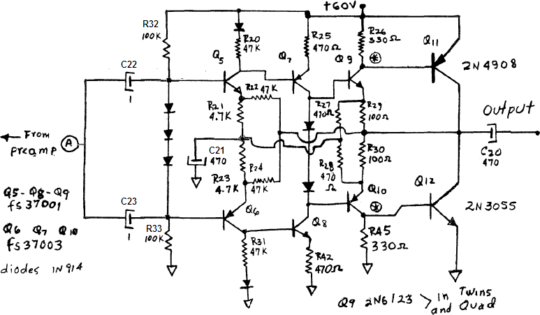


From Q7 through Q12, the circuit is identical. All of the changes center around Q5 & Q6.

o The addition of R32 & R33 to the base of Q5/Q6.

o The preamplifier input is routed through a separate cap to the base of both Q5 and Q6.

o Q5/Q6 collector resistors are now identical values of 47K.

o The addition of C21 at the junction of R21 & R23.

I have much more confidence in this circuit actually working. Just two questions:

1) Does the addition of C21 provide the common reference you though should be at the junction of R21 & R23? I think my assumption is a voltage reference.

2) It seems to me that Q9 & Q10 are expected to provide some gain. I guess I don't understand why that would lead to instability.

Thanks!!

#47
Quote from: syndromet on July 01, 2007, 03:07:32 PM
Don't really know if it fits in here, but the way runoffgroove uses jfets insted of triodes is worth mentioning. A few of those preamps sound pretty good on higher voltages.

I don't dispute what you said.

But if he mentions this, he will have to dispute the myth that Jfets sound exactly like tube triodes, or that Jfets are the solid state equivalent of tubes. It's just not true.

But hey, maybe that kind of discussion is exactly is what needed.
#48

I have a Peavey Special 130 I bought new in 1983, still works good.

It has "Saturation" which I think I remember was a tube emulation attempt. At any rate it is a pretty good sounding distortion, and better IMO than the "SuperSat" that came out afterwards.

I can see how the classification can get confusing.

I'd probably lump tube emulation under "fuzz boxes".   :lmao:
#49

Well, please understand that first and foremost I don't believe in solid state circuits emulating tubes. That whole concept implies that new technology can only exist if it remains faithful to the old.

I'm not sure if it is true about all the examples you mentioned, but it seems like only op-amp based examples to me.

How about the first company to build a solid state amp intentionally meant to be overdriven like people were overdriving tube amps? 

That would be Sunn, and in particular the Coliseum 880 - issued around 1972 I believe.

But if you want to focus only on op-amp based circuits, then you can't ignore the "cmos" technology of the Sunn Beta series. These amps are still very popular and being used today.
#50

It sounds like you are either missing a ground connection or have an improper one in the amp. Check the input jack connections first.
#51

Well, that's just too bad. Good thing I was suspicious before I built it and wasted the parts.

I guess I'll check around and see if I can find a different schematic. I got this one from musicparts.com and it's supposed to be factory. It does seem to have an incomplete or maybe sloppy feel to it - the component numbers jump around, there are holes in the sequence, some components don't have numbers just values.

Thanks for the confirmation that it won't work as drawn!!
#52

Hi,

I am having a heck of a time trying to confirm (at least in my mind) if this power amp schematic works or not. I want to perfboard build a clone of the entire amp, but I would hate to find out that the schematic is wrong. I've done lots of research over the last two weeks and this is driving me nuts.

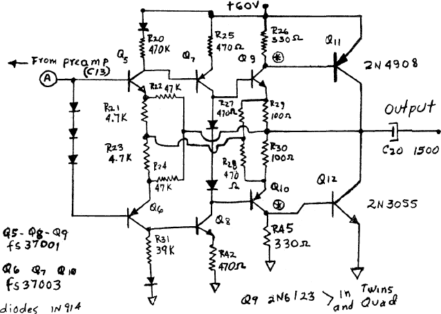
Here is the PA schematic section:


The amp is a "Mike Matthews Freedom Amp" produced by Electro-Harmonix during the early-mid 1970s. The single ended B+ supply of 60 volts was either AC derived through a minimal power supply (transformer, bridge rectifier, one electrolytic cap) and/or provided by 40 "D" cell batteries. Advertised as "100 watts peak" its RMS output is somewhere between 15 and 25 watts.

On the schematic, transistors Q5 through Q10 are indicated as either FS37001 or FS37003. I haven't been able to find a datasheet or crossreference for these numbers. However, there is an asterisk by Q9 and Q10 and a note that Q9 is replaced with a 2N6123 for the amps using more than one speaker. Since the 2N6123 is in a TO220 case and rated for 50 watts (with a 2N6126 complement) it makes some sense since they may have to provide more current to drive less than 8 ohms of the single speaker versions. So I'm assuming right now that I can find a suitable substitute using the 2N6123 characteristics.

Let me tell what I think about this circuit before I get to the problem as a mistake in my understanding may have something to do with how I got myself confused if this amp possibly works.

Q11 and Q12 is a complementary Class B output stage. No emitter resistors, but that shouldn't affect it from working. Q9 and Q10 is a complementary Class B driver stage.

Q7 and Q8 had me confused until I realized the only way it could possibly work was push-pull Class A. I assume it provides voltage amplification for the Class B drivers.

Q5 and Q6. Well obviously an input amp. Receives feedback from the output across the emitter resistors through R22 and R24. I think R27 and R28 provide a "centerline" voltage reference (~30 volts) at the junction of the emitter resistors (R21, R23). Q5 and Q6 also have to work as a phase inverter for the push-pull drive to Q7 and Q8.

Up to this point I am somewhat satisfied.

What is causing my problem is Q5 and Q6 - how are they biased? The diodes between the bases don't confuse me, I've seen those too many times like Q7 and Q8. I understand that this will set the bias between the two transistors at three diode voltage drops. I can even convince myself that the need for that third diode is to make up for the voltage drop across the series connected emitter resistors.

What totally confuses me is the lack of a DC path to establish the bias. The input is capacitively coupled. How can the base of Q5 be more positive than it's emitter when there is no source of a positive voltage at its base? How can the base of Q6 be more negative (i.e. less positive) than its emitter for the same reason? I'd be happy if there were a resistor from ground to the base of Q6 and another resistor from the base of Q5 to B+. But there isn't.

One thing that seems odd about the schematic is that the value of Q5s collector resistor isn't the same as the collector resistor of Q6. Everything else is so perfectly symmetrical with this circuit that this seems to stand out like a sore thumb, but I don't know what to make of it other than to assume Q5 needs more voltage gain than Q6 for some reason.

So, either this circuit won't work or I am totally not seeing something. I really hope it's the latter.

Any help?

Thanks
LJ