Including the changes I said in the last post, and some more to refine the mix, here is the schematic for my solid state 12AX7:

The circles there point out that there are lines in the schematic that are passing one above the other without being actually connected. As I said, RDISTORTION controls the amount of distortion for the load line (which is given by HV and the resistor connected between HV and the plate). RCURRENTGAIN controls the cathode to plate current of the device, and is set at 220 ohms to get the same current than a normal 12AX7 tube would give. Vcc should be about 4 volts higher than the highest grid voltage we want to obtain and 10V will suffice. Vdd must be at least -1V. I'm thinking of designing a voltage multiplier and current pumper that could generate those DC voltages directly using the +/-5VAC heater pins so you have that problem solved :p Ah, and those two new 1n4148 are there for correct biasing. The plate current is:

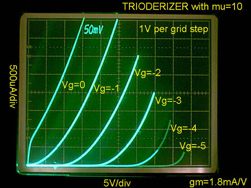
If you compare it to the graph of a real 12AX7, it is pretty much the same:

The only big difference is that for our SS12AX7, Vgs must be set up 1V higher, because grid current will start to flow at Vgs=0.5V instead of starting at Vgs=-0.5V (and that's why I added those two 1N4148). This is the graph for the grid current for RDISTORTION=9k. As I said before, RDISTORTION should be a 10k log pot:

Again, Vgk for our SS12AX7 must always be between 0.7 and 1V higher than for a normal 12AX7, so you need to rebias cathode voltage 1V lower when you connect the SS12AX7. Taking that into account, this grid current is pretty close to the real deal (if we want a more steep curve and more distortion we just have to lower RDISTORTION):

So that's all for now for the 1:1 solid state 12AX7. On the next post, I'll describe a solid state triode that works with 0 to 10V and works up to about 170mW of power dissipation instead of 1W. Ideal for stompboxes!
The circles there point out that there are lines in the schematic that are passing one above the other without being actually connected. As I said, RDISTORTION controls the amount of distortion for the load line (which is given by HV and the resistor connected between HV and the plate). RCURRENTGAIN controls the cathode to plate current of the device, and is set at 220 ohms to get the same current than a normal 12AX7 tube would give. Vcc should be about 4 volts higher than the highest grid voltage we want to obtain and 10V will suffice. Vdd must be at least -1V. I'm thinking of designing a voltage multiplier and current pumper that could generate those DC voltages directly using the +/-5VAC heater pins so you have that problem solved :p Ah, and those two new 1n4148 are there for correct biasing. The plate current is:
If you compare it to the graph of a real 12AX7, it is pretty much the same:
The only big difference is that for our SS12AX7, Vgs must be set up 1V higher, because grid current will start to flow at Vgs=0.5V instead of starting at Vgs=-0.5V (and that's why I added those two 1N4148). This is the graph for the grid current for RDISTORTION=9k. As I said before, RDISTORTION should be a 10k log pot:
Again, Vgk for our SS12AX7 must always be between 0.7 and 1V higher than for a normal 12AX7, so you need to rebias cathode voltage 1V lower when you connect the SS12AX7. Taking that into account, this grid current is pretty close to the real deal (if we want a more steep curve and more distortion we just have to lower RDISTORTION):
So that's all for now for the 1:1 solid state 12AX7. On the next post, I'll describe a solid state triode that works with 0 to 10V and works up to about 170mW of power dissipation instead of 1W. Ideal for stompboxes!