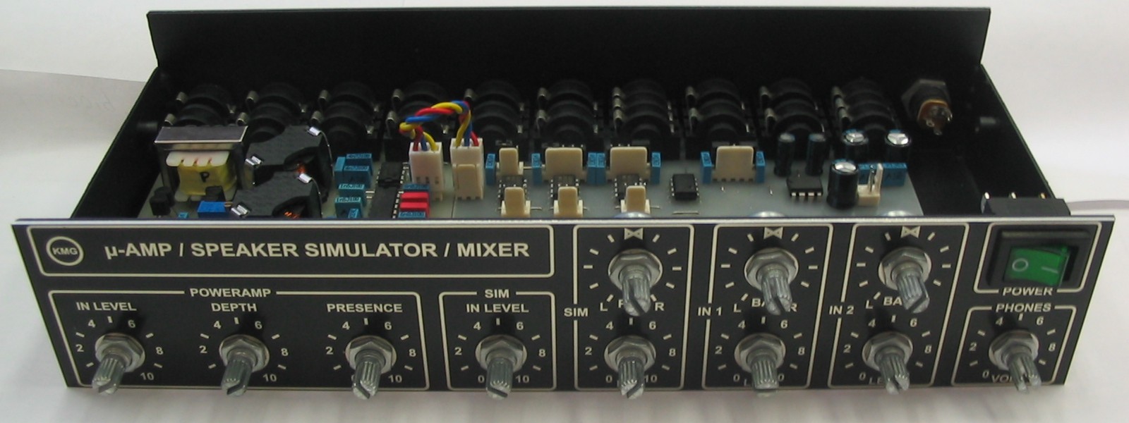
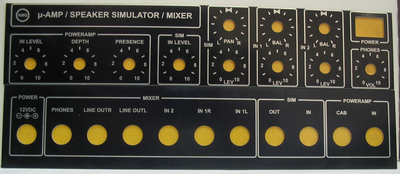
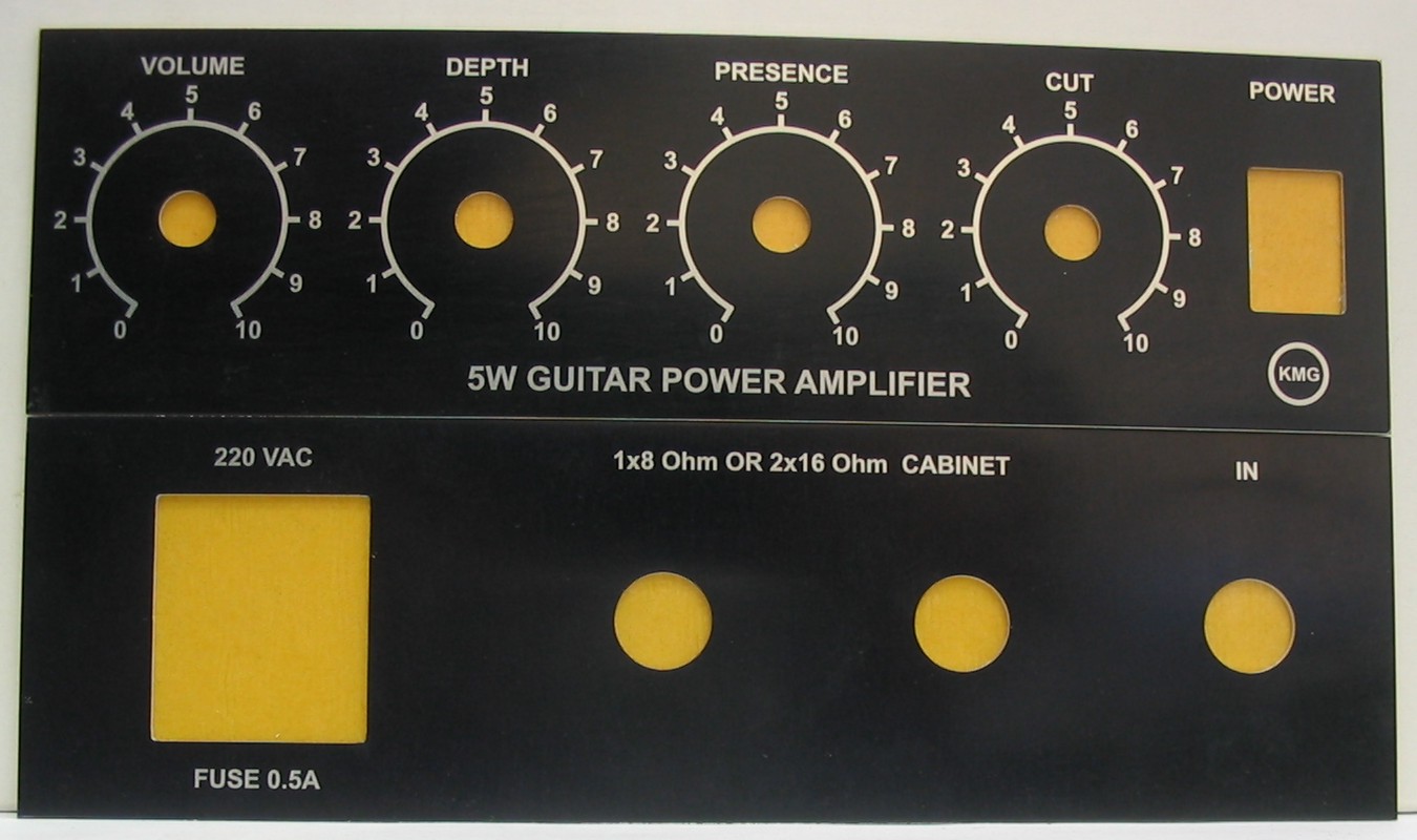
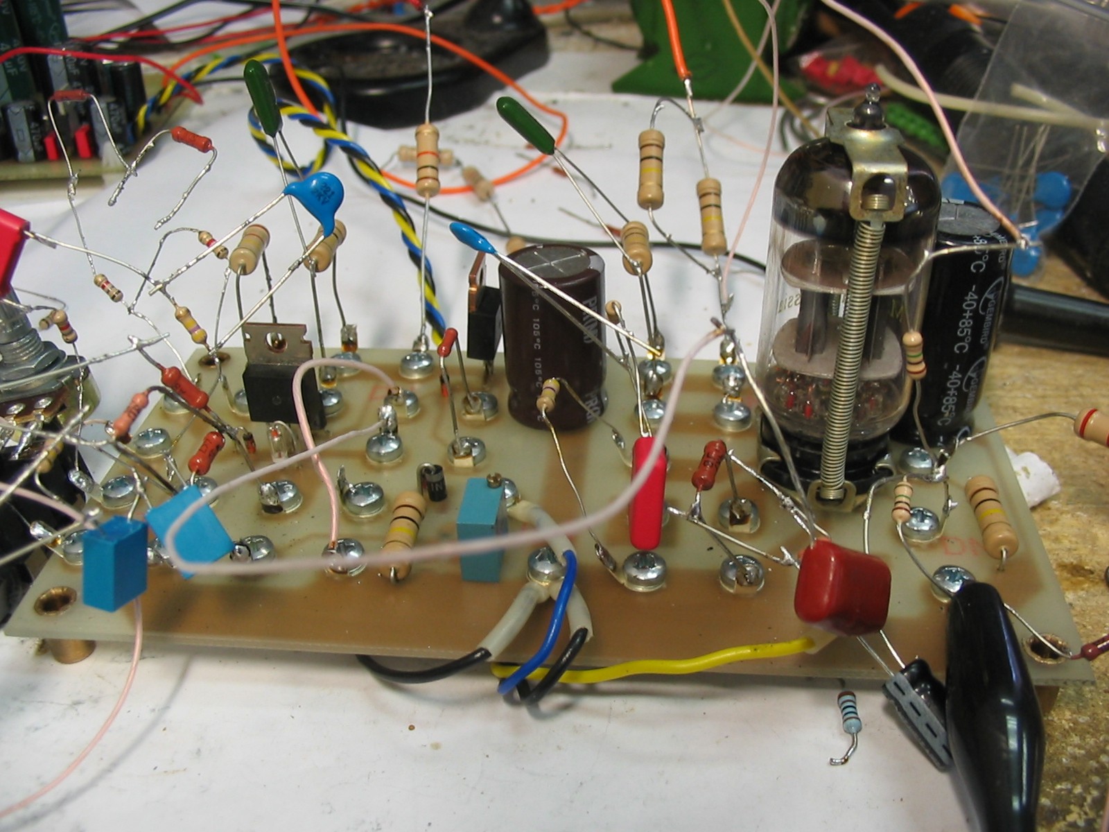
Menu

Show posts

This section allows you to view all posts made by this member. Note that you can only see posts made in areas you currently have access to.

Show posts Menu

Messages - KMG

#46
Amplifier Discussion / Re: KMG SS Poweramps
June 13, 2012, 05:12:52 AM
Assembling process.


#47
Preamps and Effects / Re: Fet version of the JCM800
June 13, 2012, 05:06:50 AM
bassetrox, it`s very bad news
I don`t find any replacement for them.
QuoteDo you think you could get similar results using vertical mosfets?
Vertical mosfets has several disadvantages - positive temperature coefficient (needs temperature compensation) & high transfer ratio.
#48
Preamps and Effects / Re: Fet version of the JCM800
June 08, 2012, 10:06:02 AM
First time "N1" was recorded SS version (fet), second "N2" - tube version.
#49
Preamps and Effects / Re: Fet version of the JCM800
June 06, 2012, 07:42:50 AM
Current consumption can be simply calculated from schematic using voltage drop on R30.
(340V - 290V) / 10K = 5mA.
#50
Amplifier Discussion / Re: KMG SS Poweramps
May 24, 2012, 12:43:28 PM
Another one microamp test.
Charvel Model 6 Orange Crackle with EMG 85 and Jackson J50BC
Chris Custom Screamer, ENGL Tube Toner e430 into KMG FET microamp (250 mW)
Randall RG75 used as Cab only
Test includes recording with Shure SM58 without cap, PA line output parallel to cab with impulse and cabsim out of microamp
http://www.youtube.com/watch?v=FDiursxnwOw
#51
Amplifier Discussion / Re: KMG SS Poweramps
April 13, 2012, 04:57:17 AM
Randall RG75 and KMG microamp in mix

http://www.youtube.com/watch?v=LM8Q6nj6vxI

ENGL Tubetoner E430, Chris Custom Screamer
Charvel Model 6 (EMG 85 and SD AHB-1), Caparison TAT
#52
Amplifier Discussion / Re: KMG SS Poweramps
April 10, 2012, 03:26:17 PM
http://www.youtube.com/watch?v=dm67Lv4KGBI
Quick test, Randal RG75 vs KMG microamp as poweramp
Charvel Model 6, ENGL Tubetoner e430, Chris Custom Screamer
Recorded with Shure SM58 (without cap) into Digilab SPM-100, slight EQ processing
KMG 250 mW prototype
#53
Amplifier Discussion / Re: KMG SS Poweramps
April 10, 2012, 09:15:04 AM
deLuther: Quick test (webcam mic) of KMG microamp prototype (250 mW)

http://www.youtube.com/watch?v=by2tYl6iqRo

Charvel Model 6 Orange Crackle (2xJackson J200+Caparison CMB3 as boost, SD Blackout AHB-1),
Chris Custom Screamer, ENGL Tubetoner e430,
KMG microamp 250 mW (prototype) into Randall RG75 cabinet
Webcam mic
Tubetoner Heavy Lead channel with TS on entire video
#54
Amplifier Discussion / Re: KMG SS Poweramps
April 04, 2012, 03:23:39 PM
Painted anodized aluminum.
This technology is more durable than silk-screening.
I ordered these panels at this company:
http://translate.google.com/translate?hl=en&sl=ru&tl=en&u=http%3A%2F%2Fm-graf.ru%2F
Big panels 9.7"x2" costs about $5 each, small 7"x2" about $3 each.
Panels are 1mm thick &  has adhesive at reverse side.
This is cheaper than laser engraving in quantities more than one.
I think you can find same companies in each country.
http://www.mpofcinci.com/anodized-aluminum-panels.html
http://www.macnameplate.com/
http://www.alumaphoto-plateco.com/products/nameplates-and-control-panels.html
....
#55
Amplifier Discussion / Re: KMG SS Poweramps
April 03, 2012, 04:10:18 PM
Got front & rear panels for micro PA+ speaker simulator +  mini mixer +  headphone amp

& 5W FET PA

Waiting for the chassis will be made for both devices.
#56
Preamps and Effects / Re: Fet version of the JCM800
March 21, 2012, 04:56:43 AM
QuoteSo.. R2 (1K), D1, D2, D3 and D4 are "SET" values to emulate the 12ax7 response right? There is no need to play with them?

What do you mean by "Point of Clipping"? the negative grid bias voltage like -1.5v in a 12ax7?
"Grid clipping point" (starting of "grid" current) defined by voltage drop on R3, forward voltage drop on D1 & fet cutoff voltage.
It`s very hard to calculate it mathematically because there is no detailed description of diode VA curve at currents about tens of microamperes.
QuoteWith what Resistor the Capacitor forms the RC filter? R?1 or R?2 or together?
Do they effect only the frequency or the grid (gate) auto-bias point also?
frequency cutoff defined by:
f = 1 / (2 * π * C * (R?1 +  R?2))
Auto-bias point defined by negative source bias voltage & DC voltage drop on R?1, R3, D2-D4.
Separete source biasing allows to independently adjust gain/frequency response & DC operating point of stage.

I don`t see the way to calculate exact stage "on paper". You can try to use simulation programs to estimate values.
I use testing board to adjust values for each kind of stage using signal generator, oscilloscope & RMAA for frequency response check.

This is old photo witn 2SK216, now I replaced them by LND150.

Only way to eliminate negative voltage at the source, is to use positive biasing of "grid" network.
But it`s not suitable for input (from guitar) stage.
#57
Preamps and Effects / Re: Fet version of the JCM800
March 20, 2012, 07:54:53 AM
QuoteR2 & D1 control how (softly/round/when) the grid is clipping when the input is reaching the bias point (-1.5)?
R2 defines "softness" of grid clipping. Voltage drop on D1 & R3 defines point of clipping.
QuoteC1 is miller capacitane emulation.
Yes.
QuoteWhat exactly D2, D3 and D4 are doing in terms of 12ax7 biasing equivalence?
As I wrote above:
Quoteshottky diodes added to source network to round sharp edges then stage enters/exits from cutoff state by summing VA curves of diodes & fets.
D4 added to protect shottky diodes from destructive breardown
QuoteR? and C2 are the same as Cathode resistor and Capacitor as in the 12ax7?
No, left resistor defines stage gain below cutoff frequency, right R defines gain above cutoff, RC defines cutoff frequency.
#58
There the full final design of LND150 JCM800 & answers to some questions
http://www.ssguitar.com/index.php?topic=2006.msg15734#msg15734
#59
Preamps and Effects / Re: Fet version of the JCM800
March 16, 2012, 07:25:34 AM
QuoteIn the source network...there is a diode called ES1J.
Google says its a silicon fast recovery. Is it crucial or would any old silicon diod do?
Germanium/shottky diodes added to source network to round sharp edges then stage enters/exits from cutoff state by summing VA curves of diodes & fets.
Then previous stage outputs full clipped voltage span, peaks on gate may be up to -160 volts.
Because LND150 has gate protection zener, fet source follows gate with voltage less than gate voltage by amount of protection zener breakdown voltage.
Diodes in source network become reverse biased. But maximum reverse voltage for BAT54 is 30 Volts. So I added high voltage fast diode to source network.
#60
Preamps and Effects / Re: Fet version of the JCM800
March 15, 2012, 04:11:56 AM
I started low voltage fet experiments with Victor Kampf idea.
http://www.sugardas.lt/~igoramps/article68/article.htm
But sound was not close enough to tube one & I moved to high voltage experiments.
First was Bogner Ecstazy preamp. Even without grid current emulation it gives results close to tube sound.
Fet version:
http://milas.spb.ru/~kmg/files/projects/xtcfet/pedal/samples/denn/kmg_xtc_mix.mp3
Tube version:
http://milas.spb.ru/~kmg/files/projects/xtcfet/pedal/samples/denn/denn_xtc_crunch_bluesmix.mp3
I tried to use Kampf`s idea with 2SK216, but in this case stage fall to FET saturation or has very fast beginning of grid limiting depending on diode biasing.
After discussing with author of this article http://gtlab.net/gtlab4/archives/216 (where this schematic http://gtlab.net/gtlab4/wp-content/uploads/2009/03/soldano1.jpg was published), I used his idea with 2SK216 & it works fine.
But I don`t tried his schematics in original.
When I start experiments with LND150 I tried to use Kampf`s idea again & it works fine with this type of FETs.
If you want to try JFET soldano you must use JFETs with cutoff voltage 0.6-0.8 Volts.
Stage tuning procedure (translated from article).
1. Set voltage at drain 6-7 Volts by adjusting source resistors (1k*).
2. Connect left pin (by schematic) of gate resistor to VSupply. Check drain voltage, it must be 2.5-3 Volts. If it high decrease resistance of R(22k*) from -bias supply, othervise increase it.