Menu

Show posts

This section allows you to view all posts made by this member. Note that you can only see posts made in areas you currently have access to.

Show posts Menu

Messages - MCM1910

#16
Updates. Got schematic from peavey. All the voltages in the power supply seem to check out. Did some more fiddling around and found that if I take preamp out to another amp it works but unfortunately plugging into the power amp there is no sound. That capacitor is a part of the power amp so I'm still thinking that is my most likely problem.

Is there any thing else I should rule out other possible causes?
#17
Quote from: Enzo on July 21, 2017, 02:58:02 PM
The light tannish goo on the caps in the picture is glue.  They smear it on the larger parts to keep them from vibrating and breaking their wire leads.

Start with the power transistors, are they shorted?  Does this unit blow fuses?  Does it produce DC on the output?  Does it even light up?

No circuit works right without proper power supply, so we always look into that first.

Get your official model name from the serial number plate, and call customer service at Peavey for the correct schematic.

Thanks for the reply Enzo! The unit does power on but does not produce any sound. What I was referring to with the cap isn't the glue but the faint trail of orange where it appears the cap let out some liquid and it was hot on the board. You can see how it affecting the area around the leads of the components next to it.

Thanks again!
#18
Amplifier Discussion / Peavey Bandit Novice repair
July 21, 2017, 02:41:26 PM
Good afternoon. I bought a peavey bandit. The original owner explained that it had an issue where it smoked. I paid next to nothing for it thinking it'd be a good opportunity for me to try out another repair.

So here is what I know. Amp listed as not working and stating that it produced smoke at one point. So first inspection I notice the power cord has had the ground prong removed and one of the prongs remaining is damaged. I opened it up expecting a lot of burnt out parts but from what I can tell there is one cap that is damaged and pretty clearly spewed some liquid out of it.

So my plan of attack here is to replace the power cord and the cap and see if that takes care of the problem. Does anyone else have any suggestions? I'm really excited to get this thing going as I've heard so many good things about these bandits!
#19
The Newcomer's Forum / Re: Improving Peavey Decade
August 08, 2016, 08:58:21 PM
Thanks very much for the explanation. I had replaced the speaker with a Jensen mod for awhile but it was still an 8" so maybe I'll try to get another larger 10 or 12" and build a cab
#20
The Newcomer's Forum / Re: Improving Peavey Decade
August 07, 2016, 10:29:14 AM
Thank you for your explanation. What about cr5 and 6. Aren't those clipping to ground? So if I'm understanding you right when plug into sat input the diodes in feedback loop are turned on and create the clipping. When I'm plugged in to the regular input and it is clipping am I then hearing more cr5 and 6?
#21
The Newcomer's Forum / Improving Peavey Decade
August 07, 2016, 12:10:16 AM
I have this little amp which seems to be so well built and sound pretty good. I find the saturation input to be really harsh though and I'm wondering if there's somethings I can do to improve it. It seems to me that the saturation input simply has a transistor boosting the signal into the opamp? Is this correct. I also see three pairs of diodes I the same signal with one set going to ground as hard clippers. Could I take these out or make them switchable? Would changing the diodes to LEDs or germaniums smooth it out?

Thanks in advance!
#22
I just thought I would update everyone on this thing, as I am still working it out...

I repaired a record player and put it into the amp.  Very low output so I took the plunge and ordered a phono preamp to see if that would help.  It did and I was able to get decent output out of it.

I'm preparing to make the enclosure.  I started by obtaining an aluminum bar which I am drilling to be a "faceplate."  I plan to make the enclosure to look similar to a guitar head and will be using pine. 

One new problem I am trying to work out is how to add an on/off lamp.  Looking at the schematic it appears the power coming off the rectifier is 22V?  Should I tap into that and then try to drop voltage (with a resistor?) to a more manageable level?  It looks like there are some points in the schematic that are labeled as around 12V, could I just tap into those spots?

As always thanks again for all your help...

Stay tuned, if I make any progress in putting it together I will post pics
#23
Sorry I missed the last few responses. It has been crazy here recently. The amp currently functions completely as designed except for some slightly scratchy pots. I'm in the process of designing a new enclosure for it now. I still haven't decided what exactly to do with it. I currently have a stereo jack wired to the input and have been listening to my iPod through it in the shop. It sounds decent...has a cool Lofi vinyl vibe...I found a really nice record player that needs some work but should be able to get up and running and I'm considering using this amp for that...

I still like the idea of using it as a guitar amp. If I do does anyone have any suggestions? ROG preamp? P27 preamp?
#24
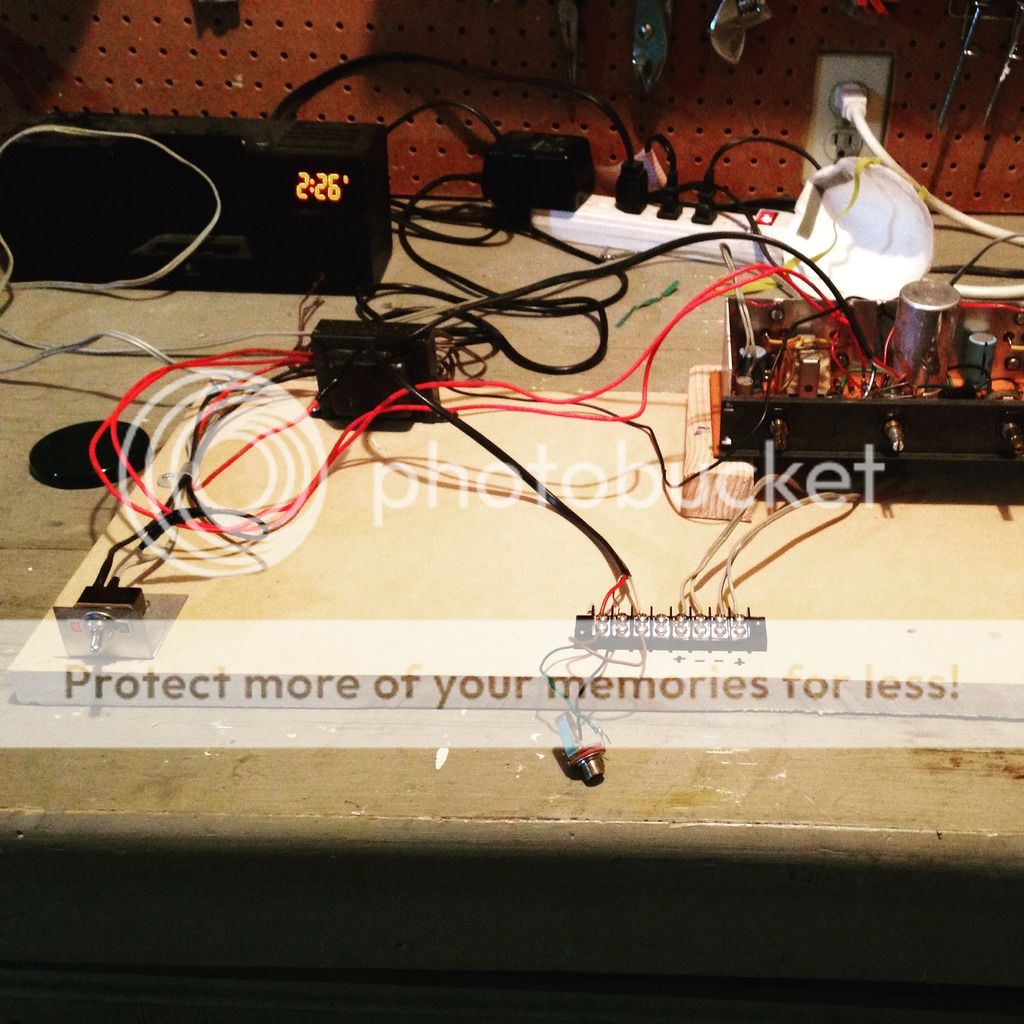
Well so here is the update.  I decided that I wanted to unhook this from the record player because as it was set up I had to turn on the old record player motor to turn on the amp.  So I disconnected it from all of that stuff and wired up a switch and added a terminal strip to this scrap of MDF to make solid connections while I was testing.  Wouldn't you know it in the process both sides of the amp started to work!  I have an idea of my error and its embarrassing but anyway it is fully functional now.  With an MP3 player feeding it, it gets reasonably loud too!

So now I am a little stuck because I'm not sure if I want to use this for a home stereo or continue with converting it into a guitar amp.  If I am to use it for guitar it will need some sort of preamp feeding it or something to boost the output.  Anyone have any thoughts or opinions on what I should do next?

Thank you for all the help!

#25
You are absolutely right I'm getting ahead of myself. I will continue to trace the circuit and report back what I find and if there are voltage problems

Thanks again!
#26
Okay so I've poked around a little bit more with it tonight.  I'm going to attach the document I was given and if I find out that I am in the wrong let me know and I will take it down.

I injected signal right before the volume control at point 35 and 14 on schematic.  With an mp3 plugged in it gave a good strong loud signal at point 35.  Point 14 didn't do much other than crackle a little bit. So I am guessing it is in the left side power amp where my problem is.

I also tried plugging my guitar into these spots hoping to bypass any preamp filtering it is doing.  Signal was much weaker than when I plugged in the front end, so I am guess ing that at that point in the circuit it wants to be fed more like line level?

Looking at the tone controls, I'm thinking that this is a baxandall tone circuit?  I've read that with the Fender tonestack you can put a switch where the mid goes to ground to bypass the controls.  Can the same be done by disconnecting the ground on the bass and treble control here?

Thanks for any help!
#27
Quote from: Enzo on June 09, 2015, 04:30:06 PM
I tell ya, I have been in electronics as a hobby and profession for over 60 years, and I have learned a zillion tricks of the trade.  Experience is a great teacher.  But the real amazing thing is that I continue to learn to this day.  Not a day goes by I don't learn something I didn't know before.

I am surprised my brain has not run out of RAM.

It is really a lot of fun, and you are right there is so much to learn!

The nice folks over at antique radio provided me with the schematic that includes a parts list and "circuitrace."  So much useful information in 6 pages.  I am tempted to post it here to get suggestions on circuit modifications but I don't want to be disrespectful to the kind person who provided me the file out of what I am assuming is his personal collection.  Would this sort of thing be frowned upon?

I will say this from the schematic I'm kind of thinking of bypassing the baxandall in preamp for some drive?  I'm assuming the baxandall has the same signal loss as the fender style tonstack?  I also think that there is a negative feedback loop.  There is a connection with a 22k ohm resistor (with a bypass cap) from the output transformer back to transistor.  I'm wondering if changing that resistor to a pot might be useful.
#28
Quote from: Enzo on June 09, 2015, 12:34:48 PM
I think your second quote was meant to be from Nosaj.

What you were doing by putting a signal in is called signal injection.  Signal tracing is listening to the circuit at various points.  All are valid techniques.  You can inject a signal at the input and follow it through the amp with a signal tracer, or you can listen to the amp output and inject a signal at various points through the circuit.  In other words if you inject a signal halfway through the circuit and it sounds OK out the speaker, then the last half of the amps is OK.  But if it sounds bad, then the problem is after the injection point.

Sorry about that you were correct that was for Nosaj.  Sorry for the error.  Thanks again for that info that makes a lot of sense. I really would like to learn the ends and outs of trouble shooting and I know I'll get much more out of it if I experience it like this. 
#29
Quote from: Enzo on June 08, 2015, 08:38:36 PM
A signal tracer is nothing more than an amplifier with a probe connected to its input.  if you have some sort of amplifier already, then connect a cable to its input, add a cap in series with it to block any DC.  Now with the free end of the cap, probe the circuit and listen to what is there.  You will also need to connect the ground of the listening amp to the ground of the unit under repair.

I see!  I was kind of doing the reverse.  I was putting an audio signal into the amplifier of the phonograph player and poking through the circuit.  I will try this too!

Quote from: Enzo on June 08, 2015, 08:38:36 PM
A signal tracer is nothing more than an amplifier with a probe connected to its input.  if you have some sort of amplifier already, then connect a cable to its input, add a cap in series with it to block any DC.  Now with the free end of the cap, probe the circuit and listen to what is there.  You will also need to connect the ground of the listening amp to the ground of the unit under repair.

It isn't a tube record player.  It is all solid state. 
#30
Thanks for posting this.  Are the recent Honeytones made with surface mount components?