Menu

Show posts

This section allows you to view all posts made by this member. Note that you can only see posts made in areas you currently have access to.

Show posts Menu

Messages - R.G.

#31
The really big difference in SS output devices compared to tubes is that bipolar transistors can die from second breakdown in microseconds. Second breakdown happens when some of the junction area gets hotter than the areas around it, and that region conducts more, with a lower voltage than the other areas. This makes it hotter, and that makes it conduct more. The phenomena is sometimes referred to as "current hogging". Old simple-structure power devices could go into second breakdown and burn a shorted hole through the die more quickly than one could sense the runaway. Modern analog bipolars have intricate internal base-emitter structures to keep current hogging postponed as long as possible.

The sudden-death failures was one reason protection was developed - sense the threshold of sudden-death just a few microns from the edge, and stop it before the transistor dies. Tube failures generally have the advantage of being much slower.

As for temperature sensing, I remember reading in Duncan's book on power amps about the world having quit waiting for semiconductor makers to include a temperature sensing diode inside a power transistor so things like proper bias and temperature sensing could be done. Recently, Sanken and On Semi have introduced exactly this, power transistors with built in temperature sensing diodes on the chip so that you don't have to try to sense what the chip is doing from the thermal distance of the case of the chip, which was the best one could do before.
But I have yet to see any designs use this. Maybe the whole design community just gave up and won't look back. Which is sad. This could have been done in the 1970s.
#32
Amplifier Discussion / Re: Haynes Jazz King
September 13, 2009, 08:40:26 AM
Quote from: Haynes_Guy on September 13, 2009, 08:21:05 AM
They are built like tanks. Any history of how it started, design people etc......?
Probably the same folks who designed and built the M1A1 Abrams...
;)
#33
Quote from: Neosho on September 11, 2009, 12:13:11 AM
I am not sure the picture is as back/white as you paint it.  I was hoping someone would reply with a link to some superior limiter design, something that was better than the typical V-I limiter.  I think we all recognize that vacuum tubes don't use V-I limiters, and when overdriven into clipping they do not usually cause smoke & flames.  So it seems to me there ought to be a SS limiter that avoids "grak" yet also protects against damage to the outputs.
Ah, so the question is really, "why can't we somehow overdrive transistor amps like tube amps and still have them live?"

OK, that's fine. It is entirely possible to do that. You just have to define what you want to happen.

First, V-I limiters are not so much intended to protect against overdrive as to protect against abusive loads. You may freely overdrive a SS amp to any degree you like with no V-I protection on it at all, as long as the reactive nature of the load does not force the output transistors into failure. Overdrive does not kill amps, at least not well-designed ones. The voltage/current/ phase on the output of the amp may do that, though. The Thomas Vox amps and others designed before about 1970 *were* sensitive to overdrive because they were marginal to start with, and were designed before people really understood second breakdown and how to both prevent it and ameliorate it (i.e. with limiters).

Second, V-I limiters are actually an economy move. The real solution to being able to drive any load, including nominal short circuits, is to keep adding output transistors to increase current output and power dissipation ability. When you add enough voltage/current capability in the output stage to drive the overload non-distructively, V-I limiting is not needed. There are, after all, solid state *welders*. However, it is much cheaper to used a few $0.05 signal transistors, resistors and diodes than to keep adding pairs of output devices at $5.00 a pair and also heatsinking to support some overload point.

Third, you need to separate issues. Making a solid state amp, any solid state amp immune to input overdrives is simple: you put a limiter ahead of the amp and feed the amp a signal that is pre-limited not to drive the amp into its own overdrive. Thomas Vox did this with their "big head" models, and many pro audio and some hifi makers have done this. The key word is "soft clip". The amp never knows it's being driven into overdrive, and indeed is not. The limiter ahead of the amp feeds the amp a pre-limited signal that's within the amp's linear range, so the amp's native clipping never surfaces.

This is different from what happens on the output when you either short the output or connect a funny load to it. Shorting the output can easily enough be handled by limiters without affecting audio, as there isn't much audio output from a short circuit to hear anyway. Funny loads are the one that needs either V-I limiting or enough output devices to drive them anyway. And actually, tubes *can* be killed by funny loads too. They're just different funny loads. As in - never run a tube amp unloaded, as this can cause an oscillation that can make the output tubes eat themselves. In fact, never run it too lightly loaded. And some loads can cause voltage spikes at the plates that arc across the tubes or tube sockets. The "protection circuits" for this tend to be either R-C snubbers across the OT primary or diode clamps to ground from the ends of the primary.

So no, the issue isn't black and white, but neither is it gray enough to simply put in a better V-I limiter. It's more purple and green.  :)
#34
A lot depends on what you consider better.

V-I limiters are not there to limit the signal from overloading the amp. They are there to prevent damage to the amp. It doesn't much matter what a damage-prevention method sounds like, if not having it means smoke and flames  - or just dead, permanent silence - pouring out of the amplifier box.

Your observations on the sound and limitations of V-I limiters are correct. So you need to ask yourself: would you rather listen to the V-I limiters sometimes inserting a bit of grak or to have to send the amplifier into the shop to have the output transistors replaced whenever the V-I limiters operated?
#35
Amplifier Discussion / Re: Need help wiring transformer
September 02, 2009, 09:02:37 AM
Quote from: J M Fahey on September 01, 2009, 10:26:46 AM
I liked your PCB, looks very professional.
Thanks!
Quote
I was thinking about concocting a simpler one, that might be made by anyone at home, single face, using iron-on transfers (or photopositive ones), no PTH, real simple.
OK, go that one done. It turns out that doing a good single sided layout was harder than doing a double sided one. I got it down to four wires and gave up. See the attachment. Note that R3, shown off the PCB, is the resistor/inductor component for decoupling the speaker at RF. It's actually on the PCB as the two concentric circles below the "R3". R3 actually stands on its end and is wound with large-gauge magnet wire to make the inductor.

I noticed some differences with the schematic that was posted. I used four times 4700uF filters, instead of six times 1500uF, so there's about twice as much filtering on the power supply. It's really possible to leave two of those off.

I didn't because I used this as a mental exercise in current-loop oriented layout. In any circuit, the DC and AC currents follow complete loops. The trick in getting a quiet layout is to think about what currents flow on a loop and then making those currents not radiate and not cause ohmic voltages for other parts of the circuit to amplify.

So on the AC power input side, I set up two current-pulse loops. Each one goes from the input AC connection to the rectifying diode, then to the first filter cap, through the cap, then back to the other side of the winding to "ground", which is ground in name only, as it's where the transformer winding CT connects. The paths to/from the filter cap carry pulses with quite high currents, maybe 10-20 times the average DC currents coming out of the cap. There are current spikes in this loop which are huge that happen 120 times per second. The rectifiers turning off can cause RF ringing  on the parasitic LC components of the traces and rectifiers. The current loop can also act as an antenna, broadcasting these pulses or their harmonics into space. Use of fast, soft recovery rectifiers can prevent diode-ringing, although with small loop size, this isn't much of a problem. But I*R voltages on the return is a problem. The currents are big enough to make millivolts of voltage across copper traces, even wide ones. It is important that your amplifier input NOT be referenced to places where the pulse voltage shows. So the return line to the CT point is isolated per cap. Even though the two caps are connected for DC purposes in the returns to CT, the current pulses will find the lowest resistance path back to its source, the CT. So isolating the return path from amplifier ground by even a longer bit of circuit traces forces the pulse voltage back to the CT.

At the second set of filter caps, the trace length to the first filter caps helps keep the highest of the pulse currents out of the actual voltage to the amplifier. This is a subtle difference, but measurable. The longer path for charge and pulse currents lessen the pulse noise on the caps that actually supply current to the amplifier. This effect could have been improved by thinner traces from the first filter cap set to the second one as long as the traces could carry the current, or by using a small, low value wirewound resistor in the non-ground path to the second filters. This could be sized to lower the DC voltage only trivially, but to reduce pulse noise quite a bit by further isolating the 120Hz pulses to the first filters.

A similar thing is going on at the second filter caps. The second pair handles its own set of half-wave-rectified pulses. These pulses are the positive and negative halves of the output signal. On the second filters side, it's not the ripple on the + and - power supplies that matter so much as it is the spikes on the return lines. So, as the author notes in the Lm3886 application note, the returns for the speaker load, output compensation filter, feedback return, at-chip filtering, and chip reference are returned by separate paths to the exact center (as much as I could!) of the center trace between the second filter caps. The speaker return gets special attention. I dinked with it for quite a while before doing the right thing: returning it to the exact center of the path between the two second filter caps. Careful measurement can show an error voltage caused by returning this current path to anyplace else. I had to use a wire for this, given the single sided board. It's clumsy, ugly, and offends my sense of elegance, but elegance is not useful if it doesn't work well, so I did it. Plowing is not elegant work, but you get to eat the grain.

I went with National's recommended 470uF of capacitance as close to the chip as I could get it. I put the mute circuit on the PCB, even though the only use of this for a guitar amp is perhaps as a standby switch.

This PCB could be adapted to a better mounting for guitar amps if one used an LM3886 with straight pins and bent the pins up perpendicular to the plane of the mounting tab so they enter the PCB from the back side. This would let you mount the PCB and chip flat on a flat-backed heat sink and have the shortest thermal path and sturdy mounting. Mounting these things on a surface at right angles to the heat sink mounting is problematical. Unless you also build a right-angle bracket for holding the PCB, there is always some flexure between the heat sink and the chassis where the PCB is bolted down. That pressure is on the soldered connections of the chip pins, and will eventually lead to failure from stress and creep of the solder joints.

#36
Amplifier Discussion / Re: Need help wiring transformer
September 01, 2009, 09:50:14 AM
I became curious about why someone could have done a circuit like that preamp. I didn't have any 2SK170s, so I ran it in the circuit simulator; easier to measure that way.

Maybe he did build one. It turns out that Idss limits the drain current and it does run.
Kind of.

With a 41V power supply, the drain voltage is 40.1V. The rms power in the transistor is 550mW, only mildly beyond it's 400mW rating, so it will run good and hot and only die sometimes. That probably improves the tone...  ;D

What's funny is that the output is visibly distorted. With a sine in, it has a nice soft squashed side and a normal side. It's got soft JFET asymmetrical distortion. I'm sure it sounds good - human ears take to soft even-order distortion like flies to honey - but it's not very accurate, nor transparent.
#37
Amplifier Discussion / Re: Need help wiring transformer
September 01, 2009, 09:14:58 AM
Quote from: J M Fahey on August 31, 2009, 02:51:58 PM
RG: solid, practical, experience-based reasoning. :tu:
This power supply (and probably many more things) come from a Mr. Carlos Filipe (carlosfm) from Lisbon, Portugal.
I was curious and tried to see some other of his brainchilds, I found his Fet preamp suggested to drive chipamps:
Wow. Words fail me. Stuff I put out may not necessarily sound like angels singing always, but it doesn't burn up.

I was intrigued by your comments on the design and looked it up. He really, really, no fooling did that. The 2SK170 specified and thoughtfully provided with a pinout diagram has an absolute maximum drain-source rating of 40V. Putting 41-42V on it as in the design MIGHT not destroy the device for some devices. Maybe.

QuoteI'm doing this for fun, but I guess I'll have to set a PayPal account and start supplying *Guitar* chipamp PCBs to our friends worldwide. Not as a business, but as a public service.
Like this? I had a few minutes and whipped that up yesterday.
#38
Quote from: armstrom on August 31, 2009, 01:51:15 PM
I don't doubt that it could be done, but could you describe in more detail (maybe a schematic?) how to wire the rectifier to produce bipolar output from the dual secondaries (as shown in the power supply in the link)? I already have one of these power supplies (with the 8 diodes) built and was considering building a second one for an additional LM3886 chip I have. If I can get away with a cheaper power supply configuration then I'll do that :)
Do this:

The board is laid out to full wave bridge rectify two independent secondaries, then to connect the positive of one of these to the negative of the other.

That's not necessary. You can connect two identical secondaries into one centertapped secondary.  This is in fact what happens in side the transformer for centertaps. When you do that, you can run the two outer legs of the CT secondary into a full wave bridge connected to two capacitor in series and connect the CT to the center of the two caps. If you then ground the CT and the two caps, you get two equal and opposite DC outputs, both of which are full wave rectified.

You can prove this to yourself by looking at the full wave rectifer in most tube amps. This uses a CT winding, but uses two diodes, each of which conduct when that half of the winding happens to be most positive. The output cap is connected between the CT (usually grounded) and the junction of the two diodes.

If you think about that for a moment, you realize that each half of the secondary winding is not conducting at all when it's going negative. Each side of the secondary is effectively a half wave rectifier, and the diodes add these together.

If you then take two diodes and another cap and hook up one diode to each half of the CT winding so the diode conducts when the winding goes negative, and connect that to an appropriately-polarized-to-ground filter cap, you get a negative supply of the same voltage as the positive one. This is the circuit that is used in 99+% of all bipolar supplies. The double-bridge rectifier circuit works, but it eats four more diodes (and you lose two more diode drops out of your DC) and cannot use a CT secondary. The single bridge rectifier circuit can use either a CT winding or two independent windings connected in series.

I've heard some noise in hifi circles about the double bridge being somehow better, but really folks - they're rectifiers! They pulse current into filter caps!
#39
Quick note. I saw your post with the link to the LM3886 amp at chipamp.com. I think this board must be an attempt to put the power supply and one channel of LM3886 on the same PCB. If so, it explains how the double-bridge power supply got there, and it validates my comments on the power supply and ground.

I'm thinking that the MUR860 double-bridge must have come from some high-end hifi theorizing; it's certainly not needed on a guitar amp. The other comments on layout apply, I think.
#40
Quote from: teemuk on August 29, 2009, 05:16:42 PM
... If it can only provide, for example, 20 watts of power then substituting a TDA2020 with a TDA2040 won't mysteriously convert the amp to a 40W amp. Even if the heatsinks were big enough to tolerate the increase, the power supply simply isn't.
That's an excellent example!
#41
Quote from: joecool85 on August 30, 2009, 11:51:47 AM
I don't have a schematic or build sheet for this one as it's a brand new prototype Brian is having me try out for him.  I'm going to email him and see if I can get him to post some insight on this thread.
I have some suggestions.
- Leave off half the diodes. You don't need them.
- Unless this is a try at super-mojo audio quality amplifiers for the Very Discerning, replace the TO-220 diodes with an integrated single-package bride. These can be had very cheaply and work very well. A 6A bridge will fit in the space of two of the TO220 diodes and probably be indistinguishable in sound quality.
- Think carefully about where the ground wire goes. Simply having copper bedsheets for ground is not always the best way to ground.
- Don't put R1 between the rows of pins on the LM3886. Sure, it could be conceptually nice to have that feedback resistor running between pins 9 and 3 there, but it's bad assembly practice, even if it fits.
- Move the i/o pads out to the edge of the PCB; especially the output pad and the input pins.
- Make a special ground pad goind to the center of the filter caps for the speaker return. Don't expect that tying the  return ground ot the "gnd" pin will keep speaker feedback off the ground line, especially if you're going to ground the input to that same hole. It looks like all the ground wires are intended to go to the "ground" terminal, possibly in anticipation of "star grounding". Unfortunately, what's set up there will mix the ground-side pulses of the power supply and the speaker return currents with the input ground if I'm reading the board right. The PCB will be exposed to hum and oscillation problems. It's possible it won't have hum or noise, because most of these things are somewhat forgiving, but there are better ways to do it.

What are the filter cap values? I'm about done with a layout of a similar circuit, but incorporating some of the things I just told you. Don't tell me what the rest of the values are.
#42
This is one of those things which seems like it should be simple, but it's not.

The correct answer to "how big a transformer do I need for a stereo LM3886 amp?" is "It depends."

It depends on the signal, of course. These amps, being Class AB, pull very little power when there is zero signal. Trivially, if you only drive it to 1W of output, you only need, say, 5W of power transformer to supply the 1W of output and maybe 4W of standing losses.

But we aren't interested in 1W outputs, are we? We want the full magilla. We want the LM3886 to put out its full 68W into 4 ohms, right?

For some background read http://www.national.com/an/AN/AN-1192.pdf, which leads you through some calculations for the single-IC case early. Putting out 60W into 4 ohms makes for 39W of power dissipation, so the total power coming out of the power supply is about 100W. That's all you need.

But as the app note explains, that's if the power supply is regulated. If it's not - and guitar, even hifi amp power supplies almost never are - then the power supply has ripple on it. (Yes, it does, with any filter capacitors of less than infinite size.) So you have to dink with the power supply to keep it above the minimum the power amp needs to avoid clipping and to avoid overtemping. You also have to worry about that max voltage rating on the chip and the fact that the AC power line rises and falls. Sometimes a lot. So we have two degrees of fuzziness thrown in with (1) no regulation and (2) AC line voltage variations.

Even assuming that we got the power supply perfect, the "60W" output is a rating based on a sine wave that's just before clipping. Not many people listen to sine waves. I have, for short periods, and they're BO-ring. We all listen to music and music does not have just-before-clipping levels all the time. Even if we have heavily fuzzed the signal. Even if we overdrive the amp like crazy. In fact, if we so overdrive the amp that it's just banging the output from rail to rail, power supply dissipation goes *down* because the amp is now dissipating much less than it would with a sine wave. The dissipation is all in the load.

Music has peaks and valleys, even heavily compressed musical instrument signals. There's a beat, or otherwise why are we doing this? That beat introduces what's called a crest factor in the music biz. The crest factor describes the peak loudness to average loudness of the signal. That's commonly 20db or more in the final music we listen to on stereos, and usually not less than 10db even in full-warp guitar or bass signals.

That being the case, the power supply is only putting out 10db below max power on average. The issue then is how long is average, and do the peaks cause problems? Power peaks do two things. (a) they cause the power supply to sag because the higher current drain causes drops through the series resistances of the power supply and (b) ripple voltage goes up because the caps drain further between recharge pulses. It is a rare power supply with so much internal resistance that it sags more than 10% from non-ripple voltage issues. So adding more *capacitors* has a much bigger band-aid effect than adding a bigger transformer.

It is possible to make a case for power transformers rated from 1/10 the nominal output power rating up to about 2X for super-duper, belt-and-suspenders, solid gold wiring kinds of amps. But the returns you get by increasing the available transformer over maybe 75% to 100% of rated power are very, very much diminishing.

Remember that a transformer's power rating is NOT the amount of power it can flow through. It's power rating is how much power it can pass through without itself overheating. And that's yet another layer of fuzziness in the power transformer sizing puzzle.

You have to decide whether you want to listen to music, buy affordable parts, or build a platinum plated, NASA space-shot amplifier. Chances are, placebo effect is going to make you happy with whatever path you choose.
;D
#43
Quote from: joecool85 on August 29, 2009, 08:51:54 PM
Pic 3 (this is the board I've been working with, and it came stuffed by Brian himself, so I'm assuming it was done correctly)
"Correctly" is not clear. That depends on intent.  :)

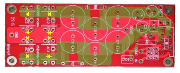
I've done some photo-retouching on the pics. The result is here:

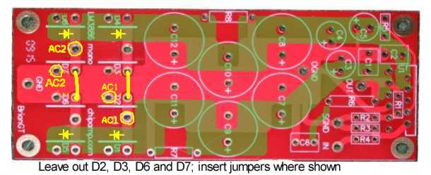
This is a top-side image with the bottom traces imposed in transparent green. Eight diodes means two bridge rectifiers. The board is set up to take either two identical transformers, a two-secondary single transformer, or a single transformer with a CT.

I think.  :)

First how to hook up your power supply. Solder the CT in that Ground hole. Solder one of your secondary wires in AC1 and the other in AC2. Either AC1 will do, as will either AC2.

In fact, there are twice as many (expensive, by the look of them) diodes on that board as are needed. You can remove four of them and just use the pads for the places where you left the diodes. For a bipolar supply, you never need to do two entire bridge rectifiers, as you can always connect up the transformers in a Full Wave Center Tap connection.

Some observations on the board:
- twice as many diodes as needed
- vastly bigger diodes than are needed, even if they're supposed to be fast/soft recovery diodes
- very, almost overly generous board layout

If this not intended to power other LM3886-only board with this power supply, it's both bigger and more expensive than it needs to be. I'm guessing that whomever laid this out is not a pro. Not that that's necessarily a problem. It'll probably work fine when put together and hooked up correctly.

Which brings to mind that the instruction sheets for this build need some updating.  :)
#44
Quote from: joecool85 on August 29, 2009, 06:31:11 PM
... the board has two holes labeled AC1 and two holes labeled AC2.  It also has a hole labeled GND.  I have 3 wires coming off my tranny, two hots and one neutral.  I split the neutral so that it went to one of the AC1 holes and one of the AC2 holes and then sent one hot wire to each of the other AC1 and AC2 holes - I didn't hook anything to GND.  All I get is a blown 1amp fuse.  So I replace the fuse with a 2amp, because thats what you normally use with an LM3886 anyway, and the tranny gets hot, the diodes get hot and the tranny hums.  And its not rectifying to DC either.

What am I doing wrong here?  Do I need to jumper some other wires and send the neutral to GND on the board?
You need to get out your ohmmeter and/or the schematic/layout of the PCB.

Mother Nature is telling you that the PCB is not what you think it is. Not knowing that PCB, I would guess that two terminals of the four in AC1 and AC2 connect to each other, and two others go from the pad on the board directly to opposite AC input sides of a bridge rectifier.

If you have a transformer with a CT, then hook the CT to either one of the two holes from AC1 and AC2 that the PCB has shorted together. Hook the non-CT wires to the other non-shorted holes in AC1 and AC2.

To save on environmentally sensitive fuses, make yourself a light bulb limiter. I *know* I've mentioned that to you before... 8-)
#45
Quote from: ponchojuan on August 29, 2009, 10:14:14 AM
Sorry to be hard on you guys, but as hackers I know you can take it. :)
Indeed we can!

QuoteIve' been an EE for over 25 years designing HPC as well as analog sensor systems including some AA designs over the years..  We EEs often get too theoretical, and less pragmatic about construction.  I apologize for my comment;  there is a lot of practical knowledge here learned by many hard knocks.
No apology needed. In my experience, there are not many of us EEs with both theoretical info and practical construction experience, even fewer left that have *analog* design experience, and even fewer with *power electronics* design experience; and of that few remaining number, remarkably few who are guitar/bass players and hackers. I designed power supplies for a living for some years, and I learned to learn from my technicians. They may not have sat through the theory, but they'd seen a lot of smoke.

QuoteMy concerns we're due to comments like designing a power supply before the amplifier.  As an engineer this sounds silly.  Pragmatically,  ICs are a cheap date so use what PS stuff is on the shelf.  I now get it.
Quite a lot of the "power supplies first" comments originated with me, in other forums. I've advised audio builders/hackers on the internet since the days of usenet, before the concepts of the world wide web. I found that many builders of audio amps sweated bullets over the abstractions of the latest supersymmetrical hyper-doozie power amp schematic, then were astounded to find that the power supply cost more and was far bigger and heavier than the amps, no matter how complicated. I deliberately tried for a short, succinct, dash-of-water-in-the-face that would get junior-apprentice audio builders to pull their heads up (or out! 8-) )

That idea may sound silly perhaps; but more importantly to me, it's startling enough to get someone to think about power supplies. And actually, in today's electronics world, the idea that a power amp is primarily a power supply with a little circuitry grafted on to let some of the power out is factually correct. Back when getting a power amp to run at all and spending the equivalent of a couple hundred of today's dollars on output transistors was a challenge, there was some justification for leaving the power supply last. But today, even if you're going to do a discrete amplifier, the power amp circuitry is going to be a trivial amount of both the cost and the complexity. It's going to come out to be about 3-6 square inches of PCB coated with parts, and power transistors stuck on a heat sink. Period.

About ten minutes in the Mouser Electronics catalog will get you all the parts except the PCB. But the enclosure, the power transformer, the filter caps, the heat sink, those are going to be hard to find and expensive. Power transformers have not seen the kind of decline in prices that power transistors have!

I was extruded through formal project management training in my last job. One of the tenets there is to put the effort where the difficulty, cost and complexity are. By concentrating early on the difficulties of powering your new 50kW amplifier, you'll be less disappointed than you would be if you built the amps and found out that the power supply can't be had for love or money.

And there's the idea of maximum upgradablility. If one has decided to build a 200W amp, then the power going into the load is defined. You know ahead of time what that is. From there, one can decide what efficiency they can practically get. A little reading in Duncan, Self, Slone, or the ones they got the theory from will show you that the efficiency of the amp divided into the output power tells you immediately both what DC power you need to provide the amp and also what power has to be dissipated in the form of heat from the amplifier, clarifying a couple of big, critical practical problems. If you don't get solutions to those problems - DC power, heat, and efficiency - you cannot and will not have a working power amplifier no matter what goes on the PCBs. But if you have a suitable power supply for a say, 200W class AB amplifier, then no matter what amplifier circuit you tag onto it, you'll have a 200w amplifier. You can upgrade the power amp circuitry and outputs much more easily than you can upgrade the power supply. Chip amps, discretes, hyper-customized solid-platinum and germanium amps, anything will go in there if you have the power supply, enclosure and heat sinking right and use the same output power and class.

Looked at from the standpoint of practical building, the amplifier is almost an afterthought. The amplifier almost does not matter.

It is **exactly** that line of reasoning that led me to buy that 100W Rogue guitar amp. I had no idea that it would be a good amplifier on its own. But if it put out 100W into two speakers (and likely 4 ohms load from that) then I already knew what the power supply was inside it. If the power transformer was not burned out and it had a suitable heat sink, it was worth the money to have a body to plant a better brain in. $40 was cheaper than I could buy a similar power transformer.

Anyway, it's a good idea to think of things from different viewpoints. In this case, IMHO building gets easier if you view amplifiers from a mechanics- and power-supply-centric viewpoint. It leads to some different and I think useful results.

Sorry to have been so hard on you. You're neither the troll nor the tyro that it sounded like at first read.