Thanks to j.m.fahey and phatt.
-Arrangements were made according to the warnings.
-Piezo and battery is far from each others
-pcb layouts were designed by me after auto routing (it must be double-checked).
-I tried to make the minimum space for the board.
-A board with 50mmx65mm sizes would fit. The rest is your ability
Of course, first i would like to test the circuit on a breadboard. It is important. Firstly test it
Quote from: phatt on October 25, 2016, 07:54:29 AM
OK you score 10 for your enthusiasm :dbtu: but don't get ahead of yourself this is not as simple as it looks.
Auto route is fine if you are making mother boards but this is not the same on several levels. 8|
For audio circuits like this auto route is the fastest way to make more land fill.
This is a very high impedance input and highly prone to picking crud noise.
Keep the input away from output.
Don't make very fine tracks and pads (I'm assuming you are going to hand etch & drill this PCB)
You are bound to end up needing to change a component and tiny tracks & pads are only good for one or two shots. There should be a global menu to set pad and track dimensions,, so use it. :tu:
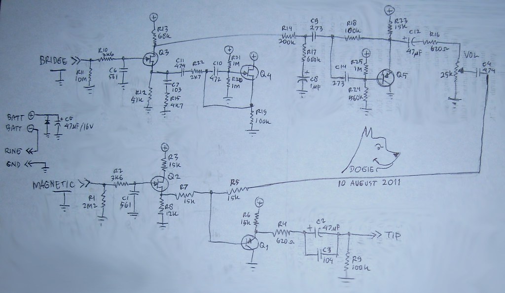
I've edited your schematic to give you some idea of how to wire it up.
Hand route the PCB and try to keep the layout much like the schematic i.e. power on one side and ground plane on the other and that should work ok for a small board like this.
Note: I changed D1 to be in series with the battery,, works either way,,, fors and against both ways.
If IRC, Diode in series puts less stress on the diode if battery is inserted wrong.
Oh the extra cap is just extra filtering and I have read it may even help the battery.
Now;
I forgot to mention,, you might want to consider an output buffer (to drive long cables better)
just a simple BJT is all that is needed. See my PhAbb Fet Boost output on previous page for how to insert that. The circuit will work without it but a buffer covers any situation.
If there is anything I've missed I'm sure others here will see any mistakes I've missed and chime in to help.
Cheers, Phil.