
I know this is way too late to reply to any of these posts but I feel I should certainly take the time out to first off apologize for not getting back to reply until now but most of all thank everyone for taking all the time they have to go in depth and explain all of these things to me. I was basically going by what I have seen done many times from runoffgroove.com in regards to mimicking and converting tube amp circuits to solid state. I thought if I kept the 15± on the opamp which is what was applied to it in the original circuit the tube to JFET section would hopefully be somewhat straight forward (throwing some pots on the FET(s) to find the correct bias) but it appears I have even FAR more to learn than I ever imagined. I know it's ridiculously late for this but now that things seem to be working properly for me here is the schematic if anyone is still interested
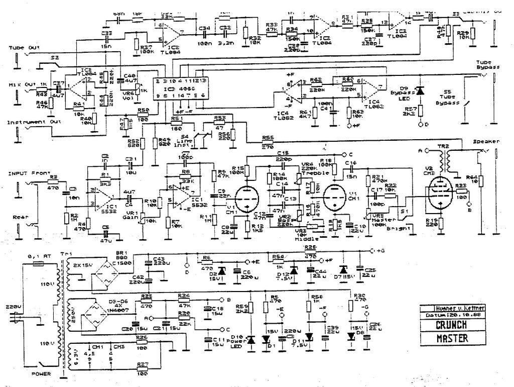
Here's the original schematic:
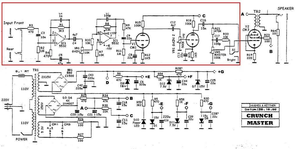
Here's a stripped down section a little doctored up with the section I was working on (circled in red):
Here's the original schematic:
Here's a stripped down section a little doctored up with the section I was working on (circled in red):
