Title: "Fender Blackface" FET preamp - anyone done this?
Post by: threefish on September 13, 2006, 06:21:21 AM
Post by: threefish on September 13, 2006, 06:21:21 AM
Hi everyone,
I'm looking for a new preamp for my lm1875-powered guitar combo - I'm after a fairly clean sound that I can put my stompboxes in front of. I've considered the Thomas Vox preamp and limiter that has appeared in discussion on this forum here (and where I first saw it diystompboxes) , but stumbled across this preamp circuit today : http://www.redcircuits.com/Page120.htm (http://www.redcircuits.com/Page120.htm).
Anyone done it? Know anything about it? Thoughts? Impressions?
Thanks
Title: Re: "Fender Blackface" FET preamp - anyone done this?
Post by: teemuk on September 13, 2006, 06:45:14 AM
Post by: teemuk on September 13, 2006, 06:45:14 AM
Haven't build it but it seems to include SRPP gain stages that have quite round clipping characters when compared to single-jfet gain circuits. The tonestack is of course the heart of the circuit so I think the "quality" of this circuit relies to fact whether it has a suitable frequency response or not. I have been pretty dissapointed to tonestack circuits on that page (Red circuits) so far... The circuit is ok (straight copy from Fender design) but IMO you'd better simulate the frequency response (for example with this: http://www.duncanamps.com/tsc/) and figure out whether you need to alter component values.
Title: Re: "Fender Blackface" FET preamp - anyone done this?
Post by: turbolx5oh on September 13, 2006, 10:33:07 AM
Post by: turbolx5oh on September 13, 2006, 10:33:07 AM
Can't help you but I've got an 1875 project that needs to be put together as well - after my 3875 project of course. Post up what you find or use. I'm interested!
Title: Re: "Fender Blackface" FET preamp - anyone done this?
Post by: Stompin_Tom on September 13, 2006, 12:20:59 PM
Post by: Stompin_Tom on September 13, 2006, 12:20:59 PM
Well, the "blackface" looks quite a bit like ROG's tonemender (http://www.runoffgroove.com/tonemender.html) but, ironically, they use fets instead of the tlc2272 chip. You could just stick the tonemender tonestack in the blackface and have more options (marshall and fender) with the added 'bonus' of fet tube tones. Does it sound better then the tonemender? Seems like the blackface would have lots more headroom and output since it runs at 18 volts or more.
I'd be interested to know what impediance and input signal level the chip power amp wants since redcircuits actually tells you that info about their circuit...
I'd be interested to know what impediance and input signal level the chip power amp wants since redcircuits actually tells you that info about their circuit...
Title: Re: "Fender Blackface" FET preamp - anyone done this?
Post by: turbolx5oh on September 21, 2006, 09:31:16 AM
Post by: turbolx5oh on September 21, 2006, 09:31:16 AM
I wonder if there is a plus/minus power supply version of either of these two?
Title: Re: "Fender Blackface" FET preamp - anyone done this?
Post by: threefish on September 22, 2006, 10:40:02 PM
Post by: threefish on September 22, 2006, 10:40:02 PM
Thanks to you all for your input.
Yes Teemuk and Tom, good points about the tonestack. I'll be experimenting with thos options you've suggested.
I'll be interested to hear the headroom offered by the 20v I have to work with - the power supply for my LM1875 poweramp is +/-20v, so I'll be running it off of the + supply rail. I know that running it off one supply rail may unbalance things a little, but I'm anticipating a really low current draw....which brings me to a +/- supply for this. My electronics knowledge doesn't extend as far as to design this conversion, but I know it would be fairly straight forward. If anyone wants to give me some clues how to do this I'd love to hear from you. I could then run it as +/- and not just +, and be able to use it all the way up to the 30v swing it appears to be capable of, not just 20v.
Title: Re: "Fender Blackface" FET preamp - anyone done this?
Post by: Stompin_Tom on September 23, 2006, 04:15:55 PM
Post by: Stompin_Tom on September 23, 2006, 04:15:55 PM
Well, I definately don't know enough to convert a circuit to +/- rails, but there might be some hints in the six band eq project over at general guitar gadgets (http://www.generalguitargadgets.com/index.php?option=content&task=view&id=216&Itemid=241). They say you can run it off either, but I don't exactly know how they're converting it. I agree, though, it does seem like it would be fairly straight forward.
I don't remember what the max volt for the tlc2272 (could look at data sheet again) in the tonemender, but I'm pretty sure it can't take too much (10v or so?). I suppose you could sub something else in there...
I don't remember what the max volt for the tlc2272 (could look at data sheet again) in the tonemender, but I'm pretty sure it can't take too much (10v or so?). I suppose you could sub something else in there...
Title: Re: "Fender Blackface" FET preamp - anyone done this?
Post by: threefish on September 28, 2006, 09:01:54 PM
Post by: threefish on September 28, 2006, 09:01:54 PM
I haven't really researched it, but I've got a few hints that converting a +v discrete circuit to +/- isn't really that straight forward as doing it with a chip circuit. I think I'll stick to my +22.5v.
Getting the parts for the circuit today. Hope to assemble next week or so. I'll post results.
Getting the parts for the circuit today. Hope to assemble next week or so. I'll post results.
Title: Re: "Fender Blackface" FET preamp - anyone done this?
Post by: didier on October 20, 2006, 06:25:05 AM
Post by: didier on October 20, 2006, 06:25:05 AM
yo
i made a pcb layout for this ss Blackface... it was done in a hurry so some thing are not ideal. (eg. pot connections...)
sometimes i feel like this software is kind of slow, but you gotta love it though.
also, this isn't verified... (also not planning to verify in the near future.)
http://www.gigafiles.co.uk/files/1414/brol/Blackface.rar
Title: Re: "Fender Blackface" FET preamp - anyone done this?
Post by: elberto on November 07, 2007, 12:08:57 AM
Post by: elberto on November 07, 2007, 12:08:57 AM
anybody build this one yet?
I'm ordering the parts now for a LM1875 amp with this as the preamp. I'll probably change the circuit somewhat--a one knob tonestack and I think I'll add the buffer further down the page.
I'm ordering the parts now for a LM1875 amp with this as the preamp. I'll probably change the circuit somewhat--a one knob tonestack and I think I'll add the buffer further down the page.
Title: Re: "Fender Blackface" FET preamp - anyone done this?
Post by: Robin755 on April 14, 2008, 08:53:25 AM
Post by: Robin755 on April 14, 2008, 08:53:25 AM
How funny, I'm actually building the same preamp with the same LM chip,
I've only tested it on an oscilloscoop and it seems to work,
just waiting for my LM chip that i've ordered, then I can fit it in my case,
I cant wait until I hear the sound coming out of it,
Has anyone build it by now?
I'm also curious what I have to do, to supply it with a +/- 20V ?
I've only tested it on an oscilloscoop and it seems to work,
just waiting for my LM chip that i've ordered, then I can fit it in my case,
I cant wait until I hear the sound coming out of it,
Has anyone build it by now?
I'm also curious what I have to do, to supply it with a +/- 20V ?
Title: Re: "Fender Blackface" FET preamp - anyone done this?
Post by: Robin755 on May 14, 2008, 06:05:12 AM
Post by: Robin755 on May 14, 2008, 06:05:12 AM
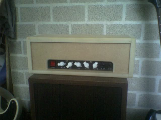
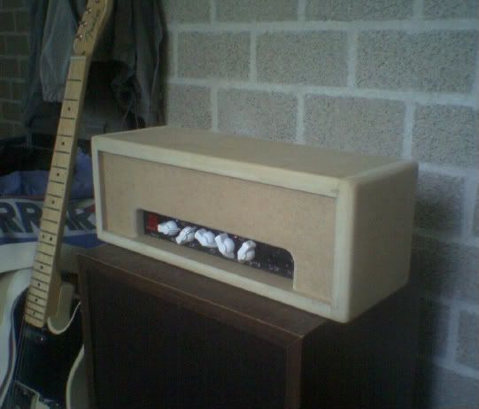
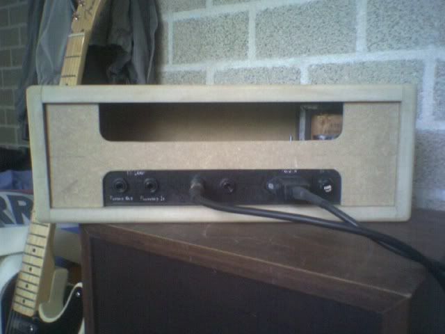
Finished, just needs a lick of paint, it really sounds great with my tele,
Title: Re: "Fender Blackface" FET preamp - anyone done this?
Post by: armstrom on May 14, 2008, 08:39:58 AM
Post by: armstrom on May 14, 2008, 08:39:58 AM
Did you end up running the circuit as-is from the positive rail of your power supply? Or were you able to convert it to use a bipolar supply?
Chassis looks great BTW. Kudos.
-Matt
Chassis looks great BTW. Kudos.
-Matt
Title: Re: "Fender Blackface" FET preamp - anyone done this?
Post by: Robin755 on May 14, 2008, 10:04:34 AM
Post by: Robin755 on May 14, 2008, 10:04:34 AM
Just feeding it with a positive voltage, I don't know how to let it work on bipolair supply
Title: Re: "Fender Blackface" FET preamp - anyone done this?
Post by: armstrom on May 14, 2008, 01:11:42 PM
Post by: armstrom on May 14, 2008, 01:11:42 PM
Great. I may give this circuit a try once my LM3886 kit from chipamps.com arrives. Do you find the tone stack adequate? The values are pretty much identical to the "default" component values listed for fender in Tone Stack Calculator.
Regarding running this off just one side of your bipolar power supply... I'm assuming there are no problems with this approach? I can't imagine what would happen, but I'm no expert!
-Matt
Regarding running this off just one side of your bipolar power supply... I'm assuming there are no problems with this approach? I can't imagine what would happen, but I'm no expert!
-Matt
Title: Re: "Fender Blackface" FET preamp - anyone done this?
Post by: Robin755 on May 15, 2008, 01:40:23 PM
Post by: Robin755 on May 15, 2008, 01:40:23 PM
No problems with running it on the +side of the supply,
the tonestack, it's ok I guess, not that experienced on that level,
if you don't like it, you can still change it by another (like the marshall one on the page)
but with my tele, it sounds quite good, nice clean tone, and good distortion,
I'm really happy with the result I'm getting,
Robin
the tonestack, it's ok I guess, not that experienced on that level,
if you don't like it, you can still change it by another (like the marshall one on the page)
but with my tele, it sounds quite good, nice clean tone, and good distortion,
I'm really happy with the result I'm getting,
Robin
Title: Re: "Fender Blackface" FET preamp - anyone done this?
Post by: J M Fahey on June 05, 2008, 11:37:39 PM
Post by: J M Fahey on June 05, 2008, 11:37:39 PM
Nice work, congratulations. Running your preamp from "only" the +B supply is no problem, you still have a lot more than enough signal to overdrive your 1875. I think you´ll have a smoother EQ range using Log pots (what Fender uses).
Title: Re: "Fender Blackface" FET preamp - anyone done this?
Post by: armstrom on June 06, 2008, 01:42:37 AM
Post by: armstrom on June 06, 2008, 01:42:37 AM
I have a question for anyone who has built this circuit... Is the schematic 100% correct? There are two crossing nets that do not show a connection on the schematic but I want to make sure they're really not connected...
I'm talking about the crossed nets right above R5 and R8 in the schematic.
So, if the schematic is correct and there is no connection at this point, how does the input signal reach the gates of Q2 and Q4? Or is this an AB style amplification stage where Q1/Q3 amplify the positive half of the input signal and Q2/Q4 amplify the negative half?
Also, if I don't care about having the low-gain input I can just ditch J1 and R2, correct? Will R3 still be required?
-Matt
Title: Re: "Fender Blackface" FET preamp - anyone done this?
Post by: teemuk on June 06, 2008, 06:40:38 AM
Post by: teemuk on June 06, 2008, 06:40:38 AM
It is actually a class-A push-pull amplifier circuit, commonly known as "SRPP". The drive signal for the upper FET is coupled from the drain of the lower FET. In this case, capacitively.
J1 and R2 can be ditched but R3 forms a RC filter together with the gate capacitance. Its effect can be extremely negligible, though, so you can toss out the resistor and see if it makes any difference.
J1 and R2 can be ditched but R3 forms a RC filter together with the gate capacitance. Its effect can be extremely negligible, though, so you can toss out the resistor and see if it makes any difference.
Title: Re: "Fender Blackface" FET preamp - anyone done this?
Post by: armstrom on June 06, 2008, 09:07:46 AM
Post by: armstrom on June 06, 2008, 09:07:46 AM
Great, thanks for the information. I like to understand how a circuit works before I build it. So far all of the circuits I've worked with (in distortion pedals) only make use of a single fet for each gain stage in a common source configuration.
-Matt
-Matt
Title: Re: "Fender Blackface" FET preamp - anyone done this?
Post by: elberto on January 20, 2009, 01:00:39 PM
Post by: elberto on January 20, 2009, 01:00:39 PM
finally got this all together. Something missing from the preamp schematic (that I needed at least) was a current limiting resistor on the supply rail. I stuck a 1k 2w in series and it's working great. lots of clean headroom, no farting out even with my humbucker equipped guitar strung with 13's, and there is a pleasant, mild grind with the volume all the way up. as I mentioned earlier I went with a modified big muff tone control instead of a TMB tonestack, and I used J201 FETs.
Title: Re: "Fender Blackface" FET preamp - anyone done this?
Post by: armstrom on January 20, 2009, 01:34:45 PM
Post by: armstrom on January 20, 2009, 01:34:45 PM
Do you have any sound clips? Also, what kind of power amp are you using?
-Matt
-Matt
Title: Re: "Fender Blackface" FET preamp - anyone done this?
Post by: elberto on January 20, 2009, 01:56:39 PM
Post by: elberto on January 20, 2009, 01:56:39 PM
no sound clips unfortunately, my recording rig is inoperable at the moment. I'm using an lm1875 power amp (kit from qkits.com).
I've been using a fender 5F4-ish amp (simpler one stage preamp and one knob tone control) and the sound is interestingly very similar through the same speaker (celestion gt-100). I would say the 5F4 has slightly rounder break-up characteristics, but I'm really digging the lm1875 + mu-amp combination.
I've been using a fender 5F4-ish amp (simpler one stage preamp and one knob tone control) and the sound is interestingly very similar through the same speaker (celestion gt-100). I would say the 5F4 has slightly rounder break-up characteristics, but I'm really digging the lm1875 + mu-amp combination.
Title: Re: "Fender Blackface" FET preamp - anyone done this?
Post by: jthank on February 04, 2009, 04:20:49 AM
Post by: jthank on February 04, 2009, 04:20:49 AM
Hi elberto,
I am planning to build the preamp with J201. Just wondering if any change in the values is needed in order to use J201. Would you give some advice? Thanks.
I am planning to build the preamp with J201. Just wondering if any change in the values is needed in order to use J201. Would you give some advice? Thanks.
Title: Re: "Fender Blackface" FET preamp - anyone done this?
Post by: Superfuzz on June 06, 2009, 08:47:07 AM
Post by: Superfuzz on June 06, 2009, 08:47:07 AM
Hey I was searching a thread like that from ages! I've came across that blackface with fet schematic so many times and I've never heard anyone who built it! There are some mods I'd like to do to it too! the first one would be to add a resistor on the upper fet source , they says it makes the output inpendance much lower (so you can drive a tonestack in a better way) then I'd put another resistor+bypass cap on the lower fet source (just for a sake of imitation of the real thing)..another nice thing to do would be adding a silent biasing network instead of the two big resistors ..asymmetrical biasing could be good too!
oh man I just want to be a better DIYer to make my first amp for real! :'(
oh man I just want to be a better DIYer to make my first amp for real! :'(
Title: Re: "Fender Blackface" FET preamp - anyone done this?
Post by: adrianhertz on February 01, 2016, 03:44:54 AM
Post by: adrianhertz on February 01, 2016, 03:44:54 AM
Hello everyone i came across this post long time ago when i was building this preamp, after some time is complete, so heres a little video i recorded, not great quality but you can hear it, no effects or anything just guitar and preamp, i"ll upload some quality record later... https://vimeo.com/153742408 (https://vimeo.com/153742408)
Sent from my iPod touch using Tapatalk
Sent from my iPod touch using Tapatalk
Title: Re: "Fender Blackface" FET preamp - anyone done this?
Post by: Loudthud on February 01, 2016, 10:36:17 PM
Post by: Loudthud on February 01, 2016, 10:36:17 PM
The same circuit was looked at in this thread:
https://www.ssguitar.com/index.php?topic=3373.0
https://www.ssguitar.com/index.php?topic=3373.0
Title: Re: "Fender Blackface" FET preamp - anyone done this?
Post by: J M Fahey on February 01, 2016, 10:59:22 PM
Post by: J M Fahey on February 01, 2016, 10:59:22 PM
Thanks for posting :tu: