Channel 1 is the second or lower preamp, the one with Supersound. Channel 2 is the first or upper preamp.
The decoupling resistors feeding all stages of the preamp from the +22V supply should be 3.3K, not 33K. 33K is correct for the tremolo oscillator.
The 33 microfarad cap feeding the channel 2 volume control should be .33 microfarad, same value as the post volume 330nf cap.
A production change to the 50 microfarad decoupling cap in the input stage of channel 1 was made in 1966, an increase to 100 microfarads to "reduce low frequency oscillation at certain settings of the controls".
Also as a production change at the same time, the 1.5K emitter resistors in the second transistors of the input stages of both channels was increased to 2.7K to "reduce the overall gain of the amplifier to value consistent with general requirements" (don't you just love engineer coverup talk? :lmao:).
Along with this "decrease the gain" change, the 47 ohm resistor in the feedback/tone control circuit of channel 2 was changed to 100 ohm.
The Reverb section. The 27K bias resistor for the input stage should be 2.7K. The reverb control is a 50K pot and is wired backwards from this diagram - the pot's wiper connects to the output/mixer gain stage through an 18K resistor before the 1 microfarad cap. (Think about what would happen if the footswitch were used with full reverb - very muddy sound).
The dry signal from the input stage emitter connects to the output/mixer stage through series connected 120K resistor and a .082 microfarad isolation cap to avoid messing up bias - not a direct connection. The output cap of the mixer stage to the power amp is a 5 microfarad value, not a 1.
The output stage driver - the 33K decoupling cap feeding the voltage amp stage is 3.3K The Custom has triple totem pole output stacks, not dual. And the speaker impedance load is 2 ohms. The .47 ohm emitter resistors are fuse wire, not actual resistors.
Supersound. Just some minor things. The two chokes are .8h not 8h.
The lower choke (as it is drawn) is not connected to the right side of the other choke - it connects directly to the junction of the .68 cap and 27K resistor... similar to the 10K in the Mid II portion - not through the switch connections. With it switched as shown, there would be no bass portion feeding through when the Mixture switch is activated (Mix is a bass/treble boost).
Unfortunately, Baldwin didn't specify transistor information. All NPNs are the same with the exception of the reverb input/driver. All PNPs are the same. The only info on the schematics is that the types need to be selected in accordance with an internal procedure reference number that varies depending on their NPNorPNP-ness (S429-1 and S438-1), with yet another for the reverb driver (S429-2). I haven't seen any of these internal procedures.
The outputs (at least for the Custom) are designated on the schematic as "TRPV", with the V being a roman numeral. They are Germanium devices.
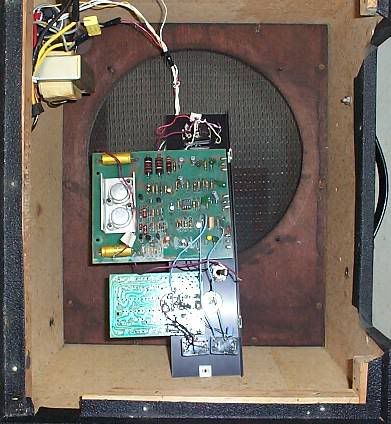
Also worthy of some note - of all these amps I've seen, maybe 12 or so - all are handwired point to point using perfboard for support.