Menu

Show posts

This section allows you to view all posts made by this member. Note that you can only see posts made in areas you currently have access to.

Show posts Menu

Messages - SJF

#1
I have some 4.7M and 10M resistors to try in my TL072 buffer  - will give it a try over weekend, and do some experiments with an acoustic with piezo. cheers again for the great assistance...
SJF

#2
Quote from: Roly on May 22, 2013, 03:14:17 PM
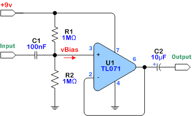
For direct input from a passive guitar you would be better off using the TL071 op-amp circuit, changing R1 and R2 to 2.2Meg to get 1Meg input resistance, and if you really need more gain than the chip amp's 30-odd dB, then altering the TL071 feedback from a voltage follower to a degree of gain.
Thanks Roly yhat has made a pretty good improvement - its starting to sound like a guitar amp. The problem I seem to be getting now is that after a few minutes of pay the cip starts to get overloaded and gets noticably distirted sound creeps in. I think Kaz mentioned that i need to get a heat sink. How does one place a heatsink on 8pin DIP on a breadboard. I have a couple small heatsinks but they require a screw/nut/washer and generally go through a pcb. Found this on the jay car website. would this be suitable  - its a type of adhesive heatsink for different package - but ???... http://www.jaycar.com.au/productView.asp?ID=HH8580
#3
Thanks Roly - what do you suggest changing the voltage divider on TL071 buffer for piezo/acoustic guitar?
#4
sorry for the late reply. Thanks guys. 

Phatt and Roly. Yes seperating the circuits and providing each with a power supply and being more carefull with my grounding has solved the oscillation issue. Thanks for that..

Kaz Kylheku - yes you are right, it completely slipped my mind. The silicon chip circuit has a heatsink. I just found a basic buffer as supplied here on the Beavis site


Would this be suitable? Will hunt down a small sink and try that this afternoon? Its a lovely cold, damp day to do electronics here :)

Here is a schematic I have done showing my version of the amp. Same as what is in the silicon chip mag but I have stuck to the stock values in the chip spec sheet for the standby and mute switches on pins 1 and 4. The silicon chip values differ because they add a transistor and switches. I just wanted the standby and mute to be off all the time. The panasonic spec sheet shows the 47k resistor going +vcc but i couldn't get it to work, it does work if grounded. May be an error??? The values on pin 2 are from the Silicon chip schematic - and they have made a vast difference to the stock amp in the spec sheet.

I have to say I'm pretty impressed with how clean and loud this amp is on just 9v supply. When I did the Silicon chip kit it came with their preamp which was tailored to dynamic mics. It didn't sound great with an electric guitar with hum buckers.

The stock amp without the preamp sounds really clean. Tried it with an EHLPB-1 clean boost. Pretty playable with the pot in the 1st quarter of a turn - anything Above that it gets a bit too overdriven/distorted - loud and feeding back.


If anyone can suggest any other changes. Will try them and report them back as well.
Happy to be making some progress - cheers all :)

I,m not sure if I would be allowed to post a copy of the silcon chip schematic??? Are there copyright issues here. Sure would be great if you guys could see that??
SJF
#5
Hi and thanks..
Yeah I originally had 2 breadboards, but a single 9v battery clip hooked to the preamp and jumpered to the other. So maybe problems there.

I ended up re-doing the whole thing on a larger multi -lane bread board that allows for separate power supplies, but again I have jumpered it all the way around so in effect it's one supply. With this setup I now get silence when the preamp is attached to the power amp???

Reason I have been attempting it that way is I now have no 9v batteries so I  rigged up an old dick smith brand multi power adapter- that puts out 3.5, 5, 9 and 12v. Chopped off the end split the lead and hooked it into the power rails via this circuit snippet http://beavisaudio.com/bboard/projects/bbp_FilteredPSU.pdf. It's working we'll and there are no noise issues with the amp. As I say it works but clips, like a lot of amps not designed for guitar input.

Will have a look and try your suggestions and report back. I think you guys may have the answer. This one has just about done my head in. But I'm here to learn  :dbtu: so it's all good.
Cheers
Steve
#6
Hi,
I joined here a while back but haven't done much electronics since then. I've got the bug again and breadboarded up a small amp based on a AN7511 chip. I read about in a silicon chip mag - "The Champion" is what they called. Its a 1-3w amp depending on voltage. Its their update to the long running "Champ" kit which was based on lm386.

Anyways I just breadboarded the stock standard amp as per the panasonic technical data sheet http://www.semicon.panasonic.co.jp/ds4/AN7511_BEB_discon.pdf
I bought a couple chips at Jaycar.

The stock amp sounds fairly nice on the breadboard but clips a bit harshly when you dig into the strings a bit.
My plan was hook up a runoffgroove fetzer valve as a preamp and see how it would improve things.

The Fetzer is working nicely on its own bread board and the An7511 amp is working nicely on its own breadboard. But when i take the output from the fetzer and insert into the Amp - I get weird oscillations only - kind of like a synth. When I turn the volume pot on the fetter i get a frequency/pitch change of the noise.

Anyone have any idea of what is going on - i,m stumped. My brain has fried. Thought i would ask you guys.
cheers
SJF
#7
Preamps and Effects / Re: DIY FUZZFACE CIRCUIT
August 29, 2011, 10:13:07 AM
Hi, new here. This thread may be dead already but seeing as I have recently been spending many frustrating hours buildinga fuzzface -  I thought I would chime in with an answer about leaky germanium transistors :grr
Yeah you can get away with using just about any germanium transistor so long as it has sufficient hFE (forward current gain).

I would suggest reading this old article by RG Keen http://www.geofex.com/article_folders/fuzzface/fffram.htm

In the article, which is well written and easy to understand for us newbs, it explains how to measure your transistors gain and actual leakage voltage. Sticking a germanium into your dmm won't cut it. In the article he shows a small schemo/diagram for setting up a test device and a couple of small calculations you need to do.

Anyway to cut a long story short hFE of 80 to 120 - is the magic number you need to make a classic fuzzface. I had a bag of germaniums AC128 (pnp) and AC176 (npn) that I got off ebay - tungsram new old stock - avoid these like the plague - as the old motto goes - buy cheap buy twice. Of the the few that had the correct gain the leakage was too high, vice versa - i think out of 50 I got 3 usable ones. I did however get the pedal going with Q1 a BC108 and AC176 in Q2 - sounds pretty good. You can get matched pairs of transistors but it'll cost $15.00 + shipping from smallbear Http://www.smallbearelec.com/Categories.bok?category=Germanium+Transistors

There is some good news about all those left over leaky transistors - apparently they can be used to make a buffer - http://www.muzique.com/news/leaky-transistor-buffer/
and as clipping diodes, so at least they will avoid becoming land-fill :)

This looks like a great forum and I will have a ton of questions for you guys for an upcoming amp build I am planning.
Hope this helps someone.
cheers
Steve