Menu

Show posts

This section allows you to view all posts made by this member. Note that you can only see posts made in areas you currently have access to.

Show posts Menu

Messages - FleshOnGear

#1
Amplifier Discussion / Re: Modding an Ampeg SS70
October 03, 2023, 10:59:57 AM
You cannot view this attachment.
Here's a bit of the guts of the Ampeg. Please excuse the messiness of some of the work. I mounted the post distortion low pass on top of the board. All of the larger film capacitors are new; the original caps were those tiny beige tic-tac looking things.

At this point I'm not quite done. I've tried some different speakers with the amp to try and thicken the tone, with some success, but I have another speaker being shipped right now. Once I've tried that one I'm going to make a final adjustment to the shelved low pass. The goal is to get the combo sounding big enough on its own without the amp becoming boomy when plugged into my extension cabs. Right now I have an Eminence Swamp Thang in the amp, and it sounds pretty good.

I'm also considering modding the amp to include the Variable Harmonic circuitry (also known as Flexwave in Crate amps). It's just two resistors, one electrolytic cap, and one diode added to the clipping stage. I'm not sure if it will really improve the sound or feel of the amp, but it seems easy enough to try.
#2
Amplifier Discussion / Re: Modding an Ampeg SS70
September 23, 2023, 05:47:05 PM
You cannot view this attachment.
[Edit: Ok, I figured out a way to get photos on here. I haven't had time to open up the amp again, but I'll try to get gut pics at some point.]

As far as whether or not this is a good platform, I think it's ok. The pcb has flimsy traces and it isn't silkscreened with part numbers, so you need to do detective work to find the part you intend to replace. The speaker it comes with, the Celestion G12K-85, is a bit bright in this amp. The shelved low pass I installed (the 68n in series with the 820 ohm resistor) worked well for the G12K-85, but made the amp too dark for other extension cabs. I had to change the 820 to a 1k5.

The are some big positives for this amp. The cabinet is sturdy. Even stock the clipping circuit is sufficiently tube-like in tone. And, these are relatively cheap on the used market. Just a few tweaks and I got a great, dynamic metal tone.
#3
Amplifier Discussion / Modding an Ampeg SS70
September 20, 2023, 01:38:56 PM
A couple months ago I bought a solid state Ampeg SS-70. Even when it's stock the amp sounds pretty great. Channel B has a really nice clean that goes into a decent crunch at higher gain settings, and channel A does the metal thing really well. The only problems with the design are that the bass and treble controls on Ch. A are pre-distortion, Ch. A is too noisy, and the pre-distortion tone filtering takes out too much treble leaving a parked wah sounding top end (even with the treble dimed) that sounded particularly dull when rolling down the guitar's volume.

Here's the schematic:

I replaced C57 (47n) with a 4n7 cap, which opened up the top end, and replaced C20 (220n) with a 330n to extend the range of boost a bit lower. Unfortunately the extended treble caused oscillation at higher treble settings, so I wired a 10k resistor from P4's CCW tab to the wiper so that C13 drops a bit of treble at higher treble settings. Now I get oscillation only at the very highest treble and gain settings. I can probably increase C57 a little to mellow the top end a bit, but I don't run the treble very high, anyway.

I replaced IC1 and IC2 (RC4558) with very low noise LT1124 op amps. This reduced hiss significantly, even with the treble boost.

I wired a 68n cap in series with an 820 ohm resistor from the node where R19 meets R20 to ground. This drops the mids and highs relative to the bass. Before that the Ch. A tone was pretty thin, but this beefed up the overall tone a lot. I also increased C15 (560p) to 1000p, to retain a bit more presence on lower mid settings.

I'm really pleased with how this turned out. When I first played the amp I could tell it had potential, that it just needed some changes to the tone filtering before and after the distortion. I wish I could change the tone controls to be after the distortion, but it would require serious rewiring, and it's kinda cool being able to control the way the lows and highs cut through the gain. The post distortion filtering I added pretty much negates the need for post EQ, anyway. With these mods I get a distortion channel that balances well with the clean channel, and the distortion cleans up really nicely from the guitar volume.

Out of my solid state amps, this one has a unique midrange voice that I really like. My Marshall 5215 has a lot of girth to the tone, fat and corpulent; the Peavey Bandit has a smooth, creamy, but punchy midrange; this Ampeg has kind of a stiff, cutting midrange that could probably tear through any band mix. I'm a fan of all of it!
#4
Sounds like a very interesting project! I just started looking into the Lab Series recently, and I'm fascinated by the CA3094 distortion circuit. The clips of the amp that I've heard sound really good, so naturally I'd love to figure out how that distortion circuit works.

Typical op amp distortion usually sounds pretty bad, IMO, though a lot of players can make those circuits sound good in recordings. I just hate the fuzzy trails on the note decay that you usually get from simply overdriving a regular op amp. I've heard a few clips of the L5 where the player was at the edge of distortion and it sounded very natural. Definitely an impressive design!
#5
I guess I never really detailed what exactly I was planning to do. Here's the schematic:

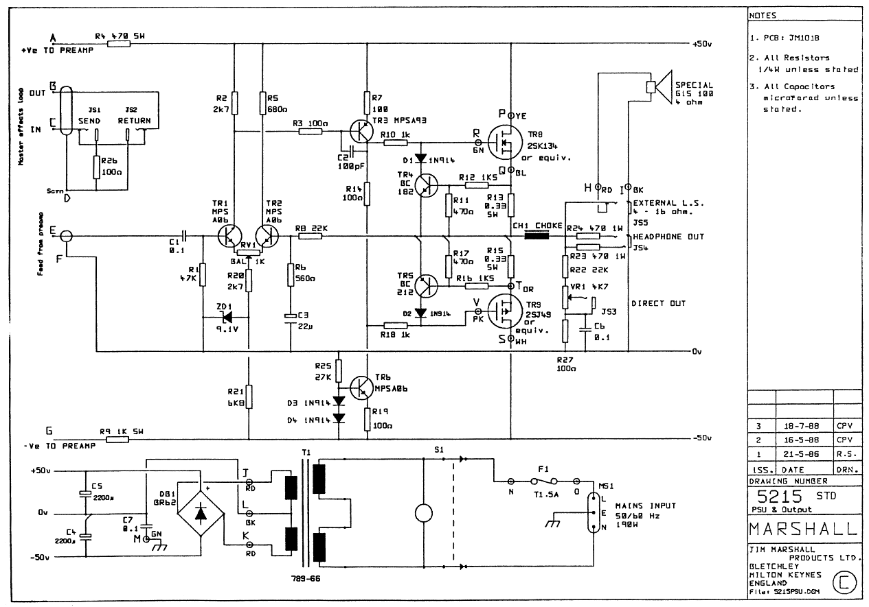
On the pcb, the negative side of the speaker wires and external speaker jack go through the headphone Jack, then there's one trace from the headphone jack that connects to the ground fill of the pcb. I cut the one trace and attached a 0.20 ohm 10W resistor from the sleeve tab of the headphone jack to ground. Originally planned on using a 0.22, but mouser was out of them.

From the connection of the 0.20 resistor and the headphone jack, I attached a 100uF cap, ran in series with a 220 ohm resistor, and wired that to the junction of R6 and R8. I changed R6 to 1k ohms. The 220 ohm resistor was originally a 330, but I replaced it with the lower value after a play test.

I will say the difference was not dramatic. The lows are definitely deeper, the highs were a bit more open. In addition to the power amp mod, I changed a couple values in the preamp to boost the treble and enhance the presence of the amp. Now it sounds quite to my liking.
#6
So, I went ahead and did the mod. It worked pretty well, and there aren't any stability issues. Thanks for letting me bounce these ideas off of you folks.
#7
Never mind about C2. I realized that it's there for stability, and that the model I was using is likely wrong.
#8
Quote from: g1 on April 09, 2023, 10:27:22 PM
Quote from: FleshOnGear on April 09, 2023, 03:21:56 PMUsing simulations, I've figured that I can get roughly 10x as much wattage at 5kHz if the output impedance of the power amp is about 12 ohms, which is about twice as loud as with pure voltage feedback.
I'm not sure what you are comparing to here, 10x more power than what? 
Turns out my math was wrong. I was distracted and had made some kind of mistake, and I was working on a bad assumption about a speaker's impedance curve.

Here's basically how I figured it, using a more accurate assumption of a 4 ohm speaker's impedance at 5kHz.

Assuming 16 ohm load impedance at 5kHz, and amp output impedance of 12 ohms:
16 ohm / (16 ohm + 12 ohm) * 14V = 8V
8V * 8V / 16 ohms = 4 watts

12 ohm output impedance into nominal 4 ohm load:
4 ohm / (4 ohm + 12 ohm) * 14V = 3.5V

Now, removing the output impedance, we assume that voltage feedback of the amp has been adjusted such that the output voltage is the same as above - 3.5V. This will give us the same power into the 4 ohm load as in the above example.

With the output impedance now zero, we can say that the output voltage stays at 3.5V no matter the load. Here's how much power now goes into the 16 ohm load impedance:
3.5V * 3.5V / 16 ohms = 0.766 watts

4 watts / 0.766 watts =
5.22 times as much power at 5kHz with the 12 ohm output impedance vs. pure voltage feedback, with equal power between examples at nominal impedance.

Sorry for the mistaken conclusion of 10x as I wrote above. This result will still be easily audible, though.

Quote from: Tassieviking on April 10, 2023, 01:49:51 AMHave you checked the power amp to see what filters are built in ?
I'm sure there are LPF's and HPF's in there somewhere, possibly to protect the speaker they used specifically in that amp combo.

C2 has a huge effect on the treble in my simulations. Looks like it's contributing to the Miller effect of TR3? That might be worth investigating.

Quote from: Tassieviking on April 10, 2023, 01:49:51 AMThe return jack on the 5215 does not go straight to the power-amp as well, it goes back to the pre-amp PCB where it goes through the effects amp and then the output amp stage, and then onto the power-amp PCB.
This looks like a good place to boost the needed frequencies.

Quote from: Tassieviking on April 10, 2023, 01:49:51 AMPerhaps you could lift the wire marked 'E' and use that to send/return to another amp just to hear the difference compared to the send/return jacks.
Nah. Those stages look like they're neutral enough. I can't be having to much fun.
#9
Quote from: phatt on April 09, 2023, 07:21:48 PMThat's ok just giving you other options, have fun with it.
Oh adding series resistance is not the same as CFB, you will just loose power.
Phil.
Yes, I will lose power, but it will give the same effect as CFB. Let's do some math.

If your amp is putting out a 12V 200hz sine wave through an 8 ohm resistor, then into a speaker at 4 ohms, 8 watts will be dissipated by the resistor and 4 watts by the speaker. If you change the frequency of the sine wave to the point where the speaker is 8 ohms, 12V across 16 ohms total is 750mA, and you'll have 6V across the speaker for 4.5 watts. Where the speaker is 12 ohms, it will be 12V across 20 ohms total for 600mA, and you'll have 7.2V across the speaker for 4.32 watts. So the wattage across the speaker stays fairly even at different impedances.

If you simply had a 4V sine output into a speaker with no resistor in between, you'd get 4 watts at 4 ohms, 2 watts at 8 ohms, and 1.33 watts at 12 ohms.

So you do lose a lot of power with the resistor, which makes it unsuitable for a permanent solution, but it will simulate the effect of CFB. It will let me know if the mod is worthwhile.
#10
Quote from: phatt on April 08, 2023, 09:42:07 AMWhy do things the hard way?
Sometimes the hard way is just more fun or interesting. It can be very gratifying to get a positive result from a modification.

Quote from: phatt on April 08, 2023, 09:42:07 AMMessing with CFB might slightly change the tone but nothing like an extra bit of EQing in the pre stages.
This might be true. As a test, I plan to simulate the effect of the modification by wiring a high power resistor in series with the speaker.

Quote from: phatt on April 08, 2023, 09:42:07 AMUsing Simulations are a great way to help you understand just how and where the tone is won and lost.
Agreed. I use circuit simulations all the time. Using simulations, I've figured that I can get roughly 10x as much wattage at 5kHz if the output impedance of the power amp is about 12 ohms, which is about twice as loud as with pure voltage feedback.

Quote from: phatt on April 08, 2023, 09:42:07 AMI still hate the idea of pedals but it's just so much simpler than trying to work inside amps,, some are a nightmare to tweak because of layout designs.
I'm not really against pedals in general, but I don't like outboard EQs as a crutch. I don't have to use EQs with any other amps I own, tube or SS. I don't necessarily agree that carrying around the extra pedal and cables is much easier than a one-time installation of 2 resistors and one cap. The layout will be the determining factor.

Quote from: phatt on April 08, 2023, 09:42:07 AMAs already mentioned, not wise to mess with a working amp. 8)
I think that depends on the knowledge, skill, and expertise of the individual designing the mods and doing the work. I have those things with tube amps and pedals. I believe I have the wisdom to know when I'm in over my head, and I'm here to gather knowledge about SS power amps so I will gain the confidence to proceed.

Quote from: phatt on April 08, 2023, 09:42:07 AMRegards to that 231Watts you worked out,,, remember that your transformer voltages would drop by a fair amount long before you got close to 150Watts. Depends on the VA rating of the Tx
Phil.
This is a good point. I have the impression, though, that the Marshall Mosfet designs are more likely to burn up their transistors than their power transformers.

As it is, I'm not ready to move forward. I have more research and testing to do, but that's part of the fun.
#11
Quote from: Loudthud on April 07, 2023, 09:06:32 PMThe big problem with the Marshall MOSFET design is that it will burn up those Hitachi FETs with little provocation. It really needs two or three pairs to be reliable. I'm not sure what it looks like inside but adding more FETs to the output could be difficult. You may be able to find some heavy duty replacements, but make sure they have SOURCE tied to the case of the TO-3. Most big FETs are TO-247 these days so you may have to improvise a heatsink.

The first thing to do to add the mixed mode feedback is to isolate the ground of the speaker and the external speaker jack.

Ok, so I'm not totally off base about the design seeming to push the transistors too hard? I could order a pair of 250W Exicons; there are still new ones available for the moment, though it looks like there may be only a few hundred out in the wild.

I haven't opened up the 5215 yet to inspect the power amp pcb. I figure the the jacks are the plastic Cliff style, so it may not be too hard to isolate the speaker jack from ground. The pcb might not be so accommodating, though. Next weekend I'll be able to take a closer look.
#12
Thanks for the welcome and the quick responses. I appreciate the links and the level-headed advice. I'll try to address as much from the above replies as I can.

I did try plugging the effects send of my 5215 into the return of my Marshall 2555, and I did the opposite as well. The 5215 preamp certainly sounded quite lively through the 2555, and the 2555 preamp sounded quite dull through the 5215. Unfortunately, the tone controls on the 2555 are after the effects loop, which skews the results. I plan to do the same test with the silver stripe Peavey Bandit that I just got this week.

I have also tried different speakers. There aren't a lot of 100W, 4-ohm 15" guitar speakers on the market. I've tried three different 15" speakers, and the best one is the stock Celestion G15B-100. I have also plugged it into my 2x12 cabinets, which sound better, but it's still dull.

I have made some modest mods to the preamp to get more presence, mainly in the tone controls. This particular 5215 is an early revision, and has a simple tone control rather than the one based on a BMT tone stack with preset bass and mids, like shown in the typical 5215 preamp schematic. I wired a treble bleed cap from the CW tab of the tone control to the wiper, so the upper treble is somewhat retained as you turn the tone down.

As far as trying to make the 5215 sound like a tube amp, that's not really my goal. The light bulb trick sounds neat, but I'm really just trying to get more wattage out of the speaker at the treble frequencies, where the impedance is rising.

I appreciate the concern for the safety of the rare MOSFETs in this amp. I actually just picked up a pair of TO-3 Exicons to swap in so I can keep the Hitachi MOSFETs safe. Of course, the Exicons have gone the way of the dodo, too. However, as I tried to explain in my OP, I have concerns about the safety of these devices in the stock amplifier.

Let's forget all about the current feedback issue, and just talk about the stock power amp for a moment. I told myself going into this that if I could figure out the parameters of the stock amp, then I could figure out how to make the mods so the amp stayed within those parameters. While analyzing this design, I found that there's really nothing to stop the user from destroying it. The preamp can supply 1.7V peak before clipping, by my figuring. But I'm also figuring that it only takes 755mV to drive the amp to the point that the current protection starts clamping down. At that point the amp is putting out 231 watts at peak.

Since I'm not experienced designing SS power amps, I'm left wondering if my analysis is wildly incorrect, and with a lot of questions about the stock 5215 design and SS amps in general. Why does the preamp appear to be so mismatched to the sensitivity of the power amp? Why wasn't the amp designed with lower voltage rails, so it would clip before reaching that amount of power? Why is the current protection set to clamp so high? Is the amp actually capable of safely providing much more output than the rated 100W into 4 ohms? How do I figure out how hard I can drive the amp before it burns out? What am I missing that makes this design make sense?

I know this is a lot, but any info you have to share is appreciated. I also plan to read Teemuk's book. I haven't found the answers in it yet, but I have only had a chance to skim it. It looks like a great resource. Thanks again.
#13
Greetings! This is my first post here, and I have a lot of questions about the possibility of modding my Marshall Mosfet 100 Reverb 5215. I tried searching for threads that touch on the relevant topics, but I didn't see much that answered my questions. I apologize if these topics have been discussed and I missed the info.

Basically, I'm thinking of modding my 5215 to add current feedback, in the hope that it will add some depth and presence to the tone. In its stock form, it sounds a bit dry, and dull on top. Here is the schematic of the power amp. I have experience with vacuum tube electronics, but less with solid state, outside of preamps and pedals.

Going into this, my main concern is that replacing some of the voltage feedback with current feedback will give the amp more gain at the extremes of the speaker's impedance curve, and that this might cause clipping with higher signals. I don't have enough experience with SS power amps to know if clipping is safe within the safe operating area of the MOSFETs. Is this a valid concern?

While researching that, I did some math on the stock power amp. It appears that it only takes 591mV peak signal to drive the power amp to full 100WRMS output into a 4 ohm load. The preamp should be able to put out almost 3x as much peak signal. Is this common? On top of that, it appears the current protection doesn't start to work until the amp is putting out 7.6A of current, which is way past the rated power of the amp into a 4 ohm load. Is this normal? Is the protection only for shorts?

It looks to me, in my limited knowledge, like the amp is already built to melt itself down if the user is just a bit too exuberant. Would using current feedback only make it more likely to be pushed beyond its limits? Can I beef up the protection circuitry to make it safer?

Thanks for reading, and thanks ahead of time for any insights.