Menu

Show posts

This section allows you to view all posts made by this member. Note that you can only see posts made in areas you currently have access to.

Show posts Menu

Messages - stormbringer

#76
Now, getting rid of trimmers sounds interesting. I know i could use trimmers to bias and then replace with resistors, but actually solving the stuff with maths before my next build and modify the design accordingly sounds both interesting, meaningful and fun, and a good step on the way of actually learning to roll my own, instead of just building other peoples designs.

Got any link with information about bias point calculations off the top of your head? Although i'm quite sure i will spend the next few hours googling anyway. :)
#77
Have actually built 3 Dr Boogeys. ^^

One with spare/scrap parts to test it, and later 2 with quality parts (1 for me, 1 for the other guitarist in my band).
Really like them, although a bit tricky tonestack, but i like trying out different circuits, you never know when you might stumble upon something awesome. :)
#78
Thanx for your input. :)

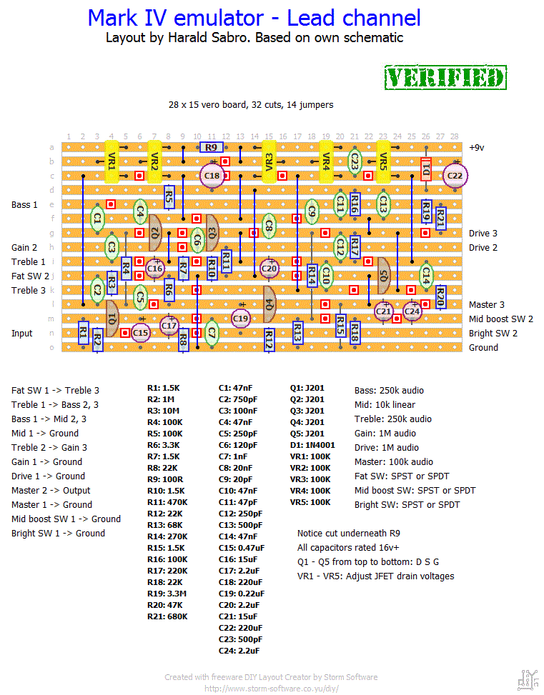
Guess i got hooked by the big "Verified"-stamp and thought it might actually work, but seeing the problems you point out here i think i'll actually scrap this one. There's some good things in this experience anyway, as i understand way more after your comments. :) Money/components spent on learning = good investment in my book.

I'm quite new, and not ready to design my own amps yet, but i'm aiming to get there, so i'm building lots of stuff found online and trying to put the pieces together. Again, thanx for your help. MUCH appreciated!

Regards
Fredrik
#79
Absolutely, he has a schematic on the site aswell. Although Component Numbers do not match his vero layout. :/


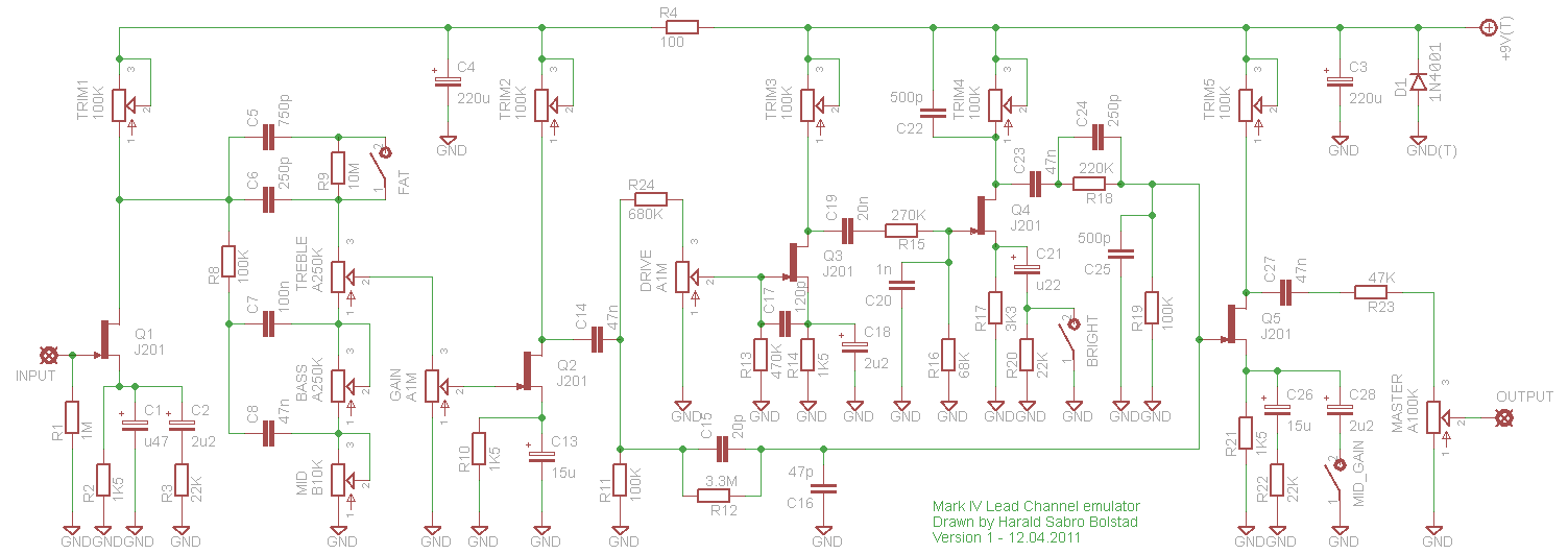
Did some more testing today, built a standard buffer and wired up before this circuit (read that it helped some people with DR Boogey oscillation issues, and this circuit not being miles away i figured i'd try the same thing, but no difference. I'm absolutely positive that the first 2 stages works perfectly, but somewhere between 2 and 3 or at stage 3 something goes terribly wrong.
#80
Hi, in my preamp building adventure i'm building and trying out alot of distortion pedals right now to gain some inspiration and knowledge finding that "perfect" (for me) dist.

The latest build is

Problem is that i can't bias Q3 to anything near 5v, about 7 it stops oscillating, but then i got this bluesy crunch instead of the wanted raw distortion. Removed all the pots + wiring and resoldered them, using shielded cable for in/out atm. Also inspected tracks with magnifying glass, reheated just about every solder joint.

To get the oscillation to stop i can go about 2 ways.
1. Turn bias on Q3 to 7v or more
2. turn drive down VERY low.

Probing around i noticed that signal is fine At R5, and on lower side of R11. C9 is oscillating terribly, so is Q3 Gate, but i'm really having a hard time finding the culprit here.. Some of these Caps are Ceramic, as i did not find film capacitors of these values. Could these be the problem? (i read about microphonic effects etc while troubleshooting). i Feel kinda stuck here.

Checklist of what's done:
1, Short wires to pots, shielded and grounded at 1 point if crossing other cable, or board.
2. Shielded input and output Wires, not remotely near eachother.
3. Q3 is the only bias that makes the circuit oscillate, can bias the other FETS any value i want more or less without problems.
#81
Also, you could try a thicker pick and strings. :)

My guitar is tuned down a full step, but with .56 - .13 strings, the pick i use is a custom 1.5 mm gripx with band logo from intuneGP. Before i got that i used a 3.0 mm, but the gripx is really sturdy, so 1.5 mm is enough not to get any "paper effect" from it. This will give you better control and feel in the long over how much the string vibrates, atleast in my opinion. :)
#82
Did go through a bunch of boss pedals. thanx for the tip! Seems i got the jfet switching up to speed now in my sim. So i'm moving on to refine the logic now.

What i was planning for my preamp is 3 channel buttons, 2 boost buttons, 1 for each of the high gain channel, and a delay switch (will include a delay instead of reverb, as i play with a mic on my amp 99 % of the time anyway, where reverb will just weaken the signal/introduce phase errors. a small delay however is nice to have during clean parts and solos.

now, this might be more complex than it needs to.. But here's how it works:

Channel 1, 2 and 3 switches are momentary, because i want separate buttons for all 3, not having to switch to channel 2, and then a toggle between 2 and 3.
Boost 1, 2 and delay could be latched, but have been made momentary in the schematic. I think this simplifies having the front panel switches in paralell with the footswitch.

Edit:
The bypass line is when no channel is selected, this behaviour is intended, as i usually stomp the high gain channel off in some riffs where there's alot of rhytmic muting to avoid monitor feedback.

The problem with the momentary switches is obviously LED indicators. I'm not really feeling up to pulling 6 extra wires out just for the LEDs. Anyone have a practical example circuit with 3 channels? I know some mesa footswitches have individual buttons for 3 channels, but havent been able to find a schematic. this circuit is just how i solved it on my own. without LEDS. Now there's probably more logic than needed. (i was actually almost ready to do this with a pic16 when i saw the IC count).
#83
Thanks for the advice there JM. I got it working in my simulator by offsetting the signal to half supply voltage! :)

Also found Teemus amazing book which helped alot! Thanks again!
#84
Thanx guys! :)

Will try this out when i get home from work!
#85
Hello.

I'm currently experimenting with a channel switching circuit. I got a working part using jfets to 1. with 0 voltage on gate let signals pass, 2. with -12 block the signal.

i have also made a circuit from 3 momentary buttons that sets a 74hc74 Flip flop to on/off for each channelwith the help of a 74hc08 quad AND Gate, while disabling the other "channels" latches. This one running on +5, output goes to a bc337 which lights a led for the currently selected channel.

But, now i need to merge the 2 circuits somehow, getting 0v when output is high on the bc337, and -12 when low, so that i can actually switch the jfet the way i want. anyone that can help me achieve this? Been googling forever...

Edit:

Just tried setting up an lm358 as a comparator, which atleast gave me +10.5 and -12 out depending on the on/off state of the bc337. But i really need to get that +10.5 down to 0, to keep the circuit from oscillating like mad.