Menu

Show posts

This section allows you to view all posts made by this member. Note that you can only see posts made in areas you currently have access to.

Show posts Menu

Messages - stormbringer

#61
Thanx Phatt, will keep an eye out. :)

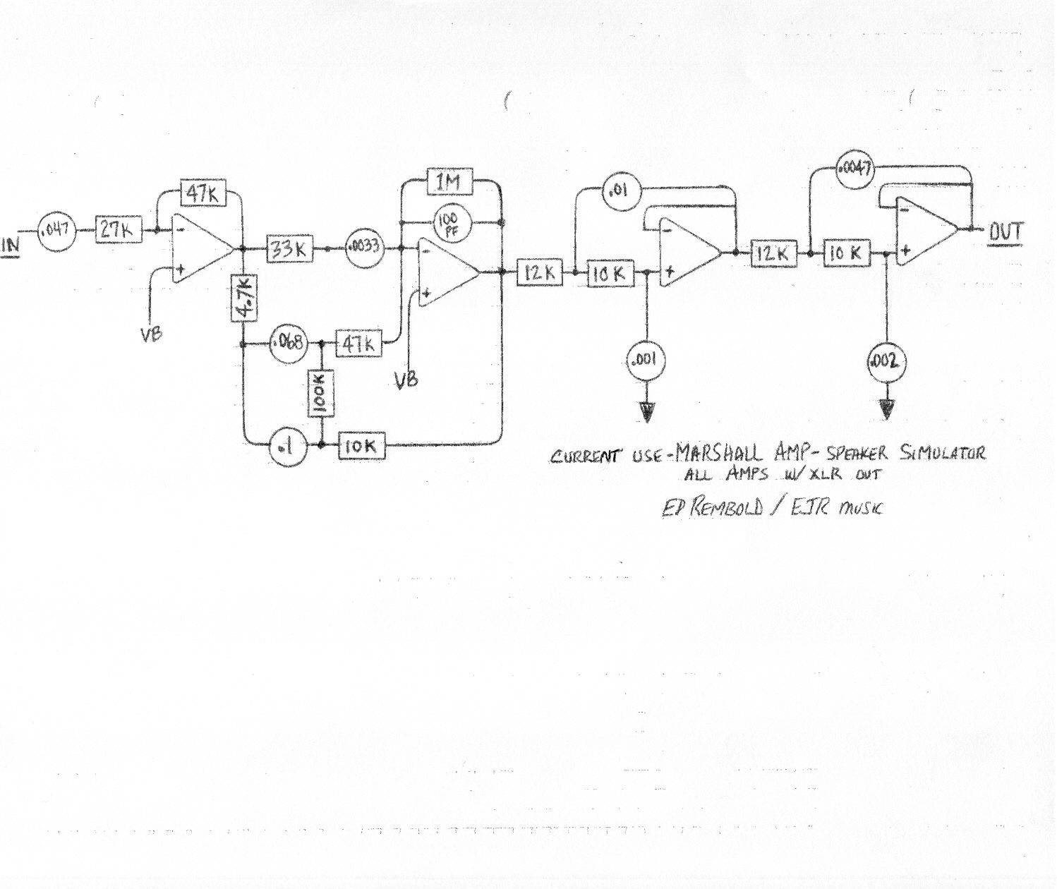
Right now i'll just go with the cabsim + tone stack i built while working on the gain stages and experimenting, later on however i will explore those parts a little deeper, right now i just needed something that worked while working on the basic parts of the preamp.

Project update:

Built a voltage doubler and hooked up a dual gang Pot to let me tune voltage between 1.5-12v from some scrap parts (well, the pot + capacitors atleast). Waiting for a LM337 to arrive so that i can complete and test it, Also found yet another AC-AC adaptor (15 VA) while searching my electronic recycling plant (Or as my girlfriend calls it, the basement, good backup in the case my 12 VA adaptor doesnt pull it off. Unless i get the awaited LM337 tomorrow i'll probably make a small voltage monitor using a pic + lcd display for the circuit. Easier tuning in voltage in a visual way than using a manual voltmeter.
#62
Yeah, outlets in kitchens and bathrooms are always grounded. And if you install new outlets anywhere nowadays they have to be, but for example in older apartments (like mine), there are no grounded outlets in the other rooms. so i usually ground myself to the radiator (they are water heated in my apartment) before handling semiconductors. Maybe it's not needed, but i havent broken anything due to ESD so far. :)
#63
Thanx for the replies guys.

I will make a test circuit for this and try it out. Oh, and i'm planning lm317/lm337 regulators. I really like those.

i'm in sweden 230v/50hz. Yeah, i got alot of respect for high currents and voltages. i always take precautions when working with electricity, even if it's not in the lethal range ie down at 5v and low current, but gaining that extra few seconds from not discharging capacitors etc just isnt worth it. Only shock i have ever had was an electric fence for horses, it was terrible. i can only imagine what (actually i dont even want to) the mains outlet would feel like.

A janitor at work got his shoulder against a rail in the roof that shouldnt even have current that caused his muscles to contract enough to break both his shoulders. No, i'm staying careful. :)
#64
Looking at various power supply solutions, and decided to do some experiments. got this AC brick that i dont use for anything. 12v, 1A AC output. More than enough current for my preamp, and i dont have to dabble with mains either until i feel more comfortable with it. Got transformer, fuses/holders and all in stock, but there's something about 230v that gives me chills down my spine, even though i have actually installed mains outlets and stuff (under the supervision of my uncle though, a certified electrician). I rather wait for that until it's time to install the entire thing in a case.

Now, according to Rod Elliot's page http://sound.westhost.com/project05.htm, a 16v AC should be able to give +/-15v using a full wave voltage doubler. and 12 VAC +/-12.

Quite interested i decided to try this out in both ltspice and Proteus. but both sims gives me around +/-11.2 VDC. Guess i will breadboard this next and see what the results are. i'm just curious to why i get these results. :)

Another question that i have been unable to find the answer to, is how i calculate maximum current with this type of circuit? It can't be as simple as just halving the AC adaptor's avaliable current?

Edit: regarding the current i found out through ltspice simulation that the capacitor values are linked to the current/ripple. so that answers my question partially, but i'm still curious about how the current draw is defined from the adaptor/transformer itself. :)
Attaching the ltspice circuit below
#65
It's an ESP LTD FX260SM with passive EMG's :)

#66
Well, here's a sound clip. Nothing special. just hooked up my homebuilt OD808 Clone before the tonestack and recorded some random riff through the sound card. first without cab sim, then with cab sim.

http://soundcloud.com/gmprog/cabsimtest-1

The cab sim schematic


Attached the tone stack aswell, it does have an added presence knob through a switch to turn it on/off + volume knob.

Using this in front of the tone stack.
Simple Jfet Buffer
#67
Went over the circuits and changed some things. removed the 3PDT switch, and added another output jack instead. So the first jack is just post tonestack out, and the other with the cabsim on. Also added a follower/buffer before the tonestack, Feeling ready to start designing and testing now. Doing it quite slow though. reading ALOT about the subject right now.

Will check back when i got something useful done. :)

As mentioned earlier, this tonestack-box is built entirely for experimenting purposes, so that i can instantly hook up the circuit under experiment and try it out, getting a bit more feel to the final result.
#68
Yeah. Already got both. :)

Guess i was a bit naive with these circuits. I'll scrap that board and rebuild just a standard tonestack for now.
#69
Oh. I took the tone stack from a project i found and built which i liked the sound from, it had that 10k resistor too, but with a JFET Follower in front of it, and 5 gain stages so high enough level to work? i see the point though. i will remove it entirely.

The Cab sim is a schematic i also have already built earlier and it did work, then again i have only been running it after buffered circuits.
found it here, i just adapted it for a TL074 instead of 2 TL072:

http://www.diystompboxes.com/pedals/schems/msim.jpg

Thanx for pointing out these mistakes. :)
#70
Haven't had that much time this weekend to work on the project, but managed to finish the Tonestack + cabsim box, gonna connect this to the breadboard while building to get an idea of what it will actually sound like. The little gem amp might be a good thing too. Thanx for the tip. :)

Attaching pictures of the tonestack box. Not the most beautiful build in town, but it works, and that's the important thing (who needs pretty lab stuff anyway? ^^), no access to a metal brake, so made a temporary one from angle iron, hinges and an old table.

Currently drawing up my USB JFET measuring device and working on firmware. Also working on the design of my power supply, will take Roly's advice and go for 24V, although this cabsim runs on 9, that's not the one i will use in the actual amp later. :)

Also decided to add Send/return to the back plate.

Note, images are quite bad. Phone camera.
#71
Thanks for the tips Roly. :)

I do have a 12-0-12 transformer scrapping around. Maybe i should use that one then. :)

Got some new parts delivered today. A bunch of useful stuff. JFets, tons of capacitors, resistors, pots etc. Stocking up for the coming experiments.

I also took a piece of scrap aluminum sheet i had and built a small box, in which i mounted 6 pots (Gain, bass, mid, treble, presence (with a switch to disable), and volume + a 1/4 jack. this will be my lab detachable tonestack while experimenting and designing. ^^  Also a marshall type cab-sim integrated inside, with a 3pdt-switch to bypass the sim and put eq directly to the jack. Easy to just hook this up to the breadboard without having pots all over the desk worrying about shorting them while playing around.

Working on the board layout right now, will put sockets for the capacitors and resistors in the tone stack for quick and easy change. Might upload a couple of pics when it's running. :)
#72
Hello, i have decided to create a thread where i will post the progress of the designing and building of this.

Hopefully other beginners will find this interesting, and that it will also give me the chance to get some help along the way with some of the mistakes i will probably make. :P

Now this is quite an ambitious project, probably bigger than recommended for someone with my limited experience and knowledge, nevertheless i'm going for it. There will be quite alot of experiments along the way. The project status right now is in the preparation for design stage.

So what's the Stormbringer Preamp supposed to become?

I'm playing in a Rock/Metal-band with female vocals, we get compared alot to Evanescense, nightwish, within temptation (mostly due to the female vocals), although i would say we got our own style, but that's really not important when it comes to this.

I use a quite limited array of sounds right now:
1. Clean with or without slight delay
2. Heavy driven distorsion for rhytm part
3. Distorsion with slight delay for leads/solos.

What i lack in my current setup, is a reliable volume boost with lifted mid for solos, currently using an analog pedal, i want this built in, inside the preamp itself, also, instead of the standard reverb, i would rather use a delay module, as it is way more useful to me when we're playing live, as i cant really use reverb directly on the amp when the rig is miked anyway.

Features:
Channel 1: clean channel with gain, bass, mid, treble and Level
Channel 2: Distorsion channel with gain, bass, mid, treble, presence and level, also switchable in to boost mode which has a Tone control + Level control, more or less a solo function.
Channel 3: Same as channel 2, but will try to color the sound a little differently between them.
Master volume, and delay, i haven't really figured out how many control knobs i'm giving it yet. Initially i was thinking about a single "blend"-control only, and lock it to 300 ms or so. But think that maybe a repeat+length control may be required anyway. Gonna have to get back to that later.

The footswitch and buttons:


  • Channel 1
  • Channel 2
  • Channel 3
  • Ch2 Boost
  • Ch3 Boost
  • Delay

I know that the amount of buttons could be lowered by making the first button toggle between 1 and 2/3 while a second button switch 2/3, and a single boost. But there's just too much stomping. on my randall RH100 this drives me nuts sometimes and makes me wanna take a riverdance class just to not get stressed when switching.

So that means i will use momentary buttons for channel 1/2/3 in the footswitch, the other could be latching.

Outputs:
Preamp Out, this goes to power amp input, i want to include a switch on the back that switches between 0.75, 1.0 and 1.25 v in order to match different input sensitivity in various power amps.
Line out with level control. A balanced line is always nice to have. Will build some rudimentary cab sim circuit here to avoid the satanic chainsaw-sound when connecting a very distorted guitar to a line.

I did some mockups on the front + back panel to get a better view of what i'm doing here. See attachments.

Power supply
i don't know yet how high voltages i need, this will require some more designing and experimenting. Will start at 12 and increase when needed.

Switching
Been looking at LDR, Relays and JFET, feeling that JFet seems to suit me best,

The Guts
JFET gain stages, i like the sound from the various j201 pedals i have built, but will try out some different JFets aswell.
the amount of stages is not yet defined, will also take some more designing.

Hopefully i got most of the information listed here, I will post whenever i got something interesting (well, that's subjective, isn't it? ;))

If you read all the way here, then thank you for your interest! :)
#73
Yeah, i figured when i get started in a proper way that i should create a development thread, where i write some kind of "diary"-like thing about the development process.

I have been reading alot, experimenting and learning. and the fetzer valve over at runoffgroove had lots of equations (as i'm working as a programmer, i love equations :P), and analyzing that got me started writing a piece of software to aid me in the biasing quest.

Right now the app works like this:
you enter min Idss and vgs_off, and max Idss/vgs_off found in the datasheet, the application then plots a chart with the selected amount of curve points for minimum, maximum and estimated intermediate values using shockley's equation.

And then it also calculates optimal bias resistor values and voltages according to the formulas on that page. Now, i'm not entirely sure how accurate those equations are, but it's really helping me understand. I'm also making a small USB HID device using a PIC18F2550 (which i have previously used to make a gameport/midi to USB-adapter). The device will be controlled from the software and read actual Idss/Vp from the socketed Jfet and draw the graph + calculate the estimated numbers.

So just insert the fet, press a button, and bam - charts and numbers based on actual values appear. :)

Now this might seem like quite an overkill for doing something as simple as a gain stage, and it probably is. But i love exploring ideas and experimenting. and with a little luck, it might actually help my designs in the future. if not.. Well.i had lots of fun making it.

But i will most likely start a new thread shortly, with that development diary from a novice's perspective.

Thanx again for your help and interest!
#74
Yes, the stormbringer amp will see the light of day some day. :) That's the goal.

Currently experimenting with that one gain stage with the 3 different jfets i got a bunch of in stock, j201, 2N5457 and MPF102. Drawing it and tuning in LTspice, then mirroring the changes on breadboard listening and recording. as i dont have a scope at the moment, I simply record through a Zoom R16 and comparing waveform amplitude in audio editing software. This is really interesting!
#75
Wow Roly, that was more than i could ever hope for! Thank you for taking time explaining and doing this!

Will start experimenting right away :D

An oscilloscope is high on the wish list, been reading about different DIY variants lately, even though buying good tools is important, i love building, You learn so much more that way. :)

Again, i feel incredibly grateful!