Menu

Show posts

This section allows you to view all posts made by this member. Note that you can only see posts made in areas you currently have access to.

Show posts Menu

Topics - blackcorvo

#1
Recently, I finished a project I've been work on and off over the last year. It's a subminiature tube amp fitted inside of a Honeytone mini amp enclosure. The original circuit board was busted beyond repair, and I had gotten some subminiature tubes to play with, so I decided to put them to good use.

Here's the final result:

https://www.youtube.com/watch?v=B79d7bydqr0

Check the video's description for the schematic, layout, pics, etc.

Or you can see those and more over here:

https://drive.google.com/open?id=1v7-ppCu_mGSNfZdqfjUrZtzhPhdUXQ48
#2
I just watched this and thought it would be well received here:

https://youtu.be/-C4EQjVDIdI

Orange finally delivers after this, ages ago:

https://youtu.be/Mg5A5xEoxRM

What are your thoughts on this? I think it's a welcome change!
#3
Recently I started working on a project that required a small, 5-volt stereo amplifier for sound, so I decided to buy a bunch of them to have a few spare ones in case anything caught fire or whatever.
After playing with one of them for a while, I decided to try and make a guitar amp out of it.

Here's the result:

Sample (Guitar: Vintage V100GT, bridge pickup)

Images of the test setup, schematic and (possible) layout in perfboard:

http://i.imgur.com/fiaXOBB.jpg
http://i.imgur.com/QOeLUjm.jpg
http://i.imgur.com/8pOCXgc.png

As funny as it may sound, the name came from me bashing my fingers on the keyboard after drawing the schematic, half-awake, at 4AM. It was not a joke about the power amp being from chinese manufacture at all.
#4
Amplifier Discussion / Black Box Amp
August 16, 2015, 10:24:27 PM
Recently I got a bunch of TBA820 ICs, and I thought about putting one of them to use in a mini amp project.

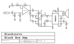
By their own they're not that great, but after putting a small preamp in front of it (borrowed from this post by PRR on diystompboxes), they actually sound pretty decent, specially through a proper guitar speaker.

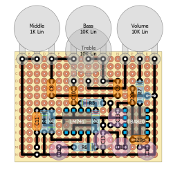
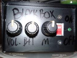
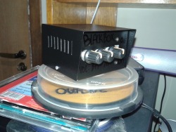
Here's the layout I'm using and the schematic, plus a couple photos of the final build (I used a dual pot for the treble+bass control due to space limitation):


It does overdrive a little, but nothing too exciting. The LM family of chips sound much better overdriven IMO. It's more of a clean amp to be used for practice with pedals or as a bench test amp.
#5
Preamps and Effects / Monarchy Drive
August 14, 2015, 01:51:11 AM
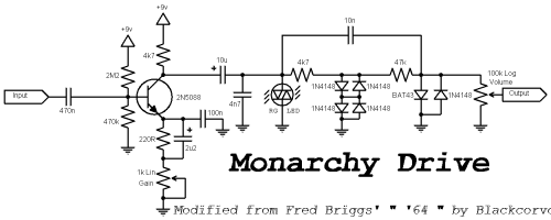
I stumbled upon this circuit the other day, and since Vox amps always had one of my favourite types of tone of all time, I decided to try his circuit.
But, to be honest, the sound didn't cut it for me. The Headroom control was specially not that great to my ears. Sounded too much like crossover distortion when not at it's minimum setting, which I am not a big fan of.

So, I experimented for a while and I ended up with this:


It has a much more dynamic (i.e. gradual) distortion, a little more gain and compression, and a much closer sound to what Vox amps sound like (to my ears).

The idea is that, by cascading the clipping circuit using diodes of different voltage drops, you can simulate the gradual, cumulative type of distortion that happens on a tube amp. Each clipping stage simulates a different stage on the amp (the bicolor RG LED would be the preamp, the 4x 1N4148 are the phase inverter, and finally the BAT43+1N4148 is the power amp).

Plus, you get a cool "clipping" indicator with that bicolor LED.
#6
So, the other day I decided to open up my lovely Honeytone amp to do a couple mods. Added a speaker out jack and a rechargable battery pack to it.

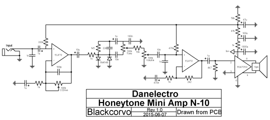
In the middle of it, I noticed the resistors for the second op-amp had different values from the schematics I've seen online (1k/2k2 instead of 2x 33k), so I decided to correct that.
Before doing so, I looked up other sources to confirm the values were up-to-date and I had my confirmation here http://batterypoweredguitaramp.com/danelectro-honeytone-guitar-amplifier/.
But instead of just correcting the already drawn schematic, I said screw it and just drew the whole thing again.
I ommited the LED and On/Off switch for simplicity, as this is only a reference circuit.

Here's the schematic:


I'll be attaching the picture as well, just in case the source links for it get lost in time.

And in case anybody is curious about the mods, I have made a post on my tumblr about it
http://blackcorvo.tumblr.com/post/120898269985

And also a quick demo video of the finished product through a 10" speaker
https://www.youtube.com/watch?v=7KAEKuLByUc

I like this amp's circuit enough that I'm seriously considering cloning it, but using a TDA7240 for the power amp. Maybe when I get the materials for producing PCBs? We'll see.
#7
So, I bought a Vox Pathfinder 10 this week in pretty good shape. Looks brand new, came in the original box and everything. Then I tried playing with it...

With the switch on clean it sounded nice, but once I tried using the drive it sounded really crappy. It also had a bad treble pot (it scratched and cut out the sound between zero and 1/2 way on the knob). So, I opened it to see what I could do about the pot.

Surprise surprise, someone modded it putting two diodes in place of the LEDs (ge and si), and did a very crappy job too. The pads in the pcb for the LEDs were pretty much history. I think only one diode was actually in contact with the copper and that explained the crappy drive sound.
Thankfully I was able to restore it to have the original red LEDs in there and it sounds much better now! Then I put a 100k pot replacing the bad 50k (that's what I had available). Really digging it now!!!

But after all that, I remembered the oh so famous LED mod some people do, where you would remove the LEDs from the circuit to get a more "natural" sound. I discovered you can achieve that without having to open the amp!

Simply slide a piece of plastic or metal in the space between the drive switch knob and the hole in the chassis so it stays in place when you move it (before it clicks). Slowly push it until you find the sweet spot where the LEDs are not switched in but the boost is active. Boom, LED mod without even touching a screwdriver!
#8
Tubes and Hybrids / Meet the PushOver
October 21, 2014, 07:43:27 AM
Hey guys! Here's yet another project I wanted to share with you. Got some tubes a couple weeks ago (4x 12AQ5's, 2x 6AQ5's, and 8x 6J6's) because I wanted to put some ideas I had a while ago into practice. One of them is in the following schematic:

http://i.imgur.com/r0vhfWe.png

It's a simple circuit that I wanna try out soon. Haven't had time to try it out yet, but I will get to it when I can. I also had a couple ideas for the chassis this amp could have, but I'm probably gonna do something completely different from them (I don't know where I could get either of them made, so I'll just do something else instead).

http://i.imgur.com/JFljkGC.png
http://i.imgur.com/bjtoB8K.png

I'll update as go along.

[UPDATE]

Had an idea for a cabinet based around a 6" speaker. It's simple enough to adjust the dimensions of the box for any other speaker size tho, and could be used either for a cabinet or a combo.

http://i.imgur.com/i0TCZvY.png
http://i.imgur.com/ecz5X9W.png
http://i.imgur.com/Tw28fdt.png
http://i.imgur.com/smOnP55.png
#9
Preamps and Effects / Voxer '49 - CD4049UBE-based preamp
February 23, 2014, 01:16:26 PM
Hello there guys! I'm back with yet another strange idea: a CMOS-based preamp. Specifically, I'm using the CD4049UBE, and this is the circuit I ended up with after a good couple of days playing with values.

Here's the schematic:

https://24.media.tumblr.com/6c7488cbc33f0f0085410e599d359fcc/tumblr_n1gmusrwOY1r4gqjso2_1280.png

It's pretty much just a Runoffgroove "3 Legged Dog", but without the input JFET booster, and  the addition of a tone control.

I went ahead and recorded a few samples using Audacity, and just to have an idea of what it might sound through a guitar cab, I used Amplitube to simulate a 1x6 combo cab, and a 2x12 Vox-style cab. Both cabs were recorded with a Dynamic 57 right at the speaker, in the cone position. The tonality change is made via the "Mic" control on the circuit, going from brighter to darker (on the knob, in the order 0, 2.5, 5, 7.5 and 10).

First, the original dry sound: https://soundcloud.com/corvolino03/sets/voxer-49-dry
1x6 cabinet simulation: https://soundcloud.com/corvolino03/sets/voxer-49-preamp
2x12 cabinet simulation: https://soundcloud.com/corvolino03/sets/voxer-49-preamp-1

And last but not least, a PCB layout made in DIY Layout Creator:

https://31.media.tumblr.com/ef2b084f91651e705a178fea2fa87f97/tumblr_n1gmusrwOY1r4gqjso1_1280.png
#10
Tubes and Hybrids / Pristine - 7-pin Princeton 5C2
February 12, 2014, 10:55:10 PM
Hello!

I wanted to share with you guys a small project I made some time ago. It's a 7-pin version of the Fender Princeton model 5C2. For this, I used a 6AQ5 power tube and a 6J6 as the preamp tube, and god some nice vintage-y sounds from it!

Here's the schematic:

http://imageshack.com/a/img855/6201/23xz.png

And here, a video demo of it:

http://youtu.be/qJVdgweHezY?t=1m

I used the alternative power supply for the final circuit, because I wasn't able to get a proper tube PT.
#11
Hello there once again!
It's been some time since I've last posted (had some family stuff to take care of), but I'm back!

Recently, I've been playing with some low-watt tube circuits, but because of my lack of proper power and output transformers, none of them went very far. Also, they take a little too much effort to put together.
So, I decided to try out something else: a portable, solid-state amp.

From my tests, I discovered that I don't need more than 10w to play at home, so I got myself a TDA2003, and I'd like to use it for a small combo. BUT, I've done some tests with the standard datasheet circuit, and it distorts way too easily!
If I understood the gain formula correctly, the circuit has a gain of 100x using the standard values for the gain resistors (220R and 2R2).

I don't need that much gain, specially if I plan to use a preamp in front of that chip!

It said in the datasheet that the 220R resistor controls the current draw (lower = higher current draw), and I don't wanna mess with that.
Could I instead use a larger value for the 2R2 resistor to reduce the gain?

Thanks ahead for any help/information on the subject!
#12
Tubes and Hybrids / Small Push-Pull Amplifier
November 23, 2012, 12:37:49 AM
So, I started working on a small project to put in use some tubes I had laying around.

Here's a little clip I recorded a couple days ago:
http://www.youtube.com/watch?v=vBoPgQ0By90

And here's the schematic:


The 5AQ5 is simply a 6AQ5 with a 4.7v/600mA filament. All other specs (plate dissipation, max voltages and curves) are the same.
The switch maked with "150v" and "280v" simply changes the B+, so I can get crunchy tones at lower levels (as I've shown in the video).

I am also planning on adding a second power section using a bridged TDA2005 (that would be powered by rectifying the AC from the filament secondary), for louder clean tones.
After checking the Datasheet for it, I came up with the following circuit (STILL UNTESTED) :


I would connect each input to both sides that feed the 5AQ5s grids.

The speaker would be connected to a DPDT switch, to change it from being connected to the tube PA or the SS PA. I would also have a 100R resistor connected to the OT's secondary, so that I didn't end up blowing my power tubes when switching to SS mode.

What do you guys think? I'm sorry if it sounds confusing... but I sometimes overthink a little when coming up with ideas like this one.