Title: acoustic 150 zobel?
Post by: ilyaa on April 15, 2015, 09:20:04 PM
Post by: ilyaa on April 15, 2015, 09:20:04 PM
am i write to say that R404 and C404 make a zobel network across the output?
what would cause R404 to blow? my guess: amp plugged in without a load puts the output wattage across the puny 1W R404 and blows it up -
but then isnt that resistor just asking to be destroyed? ive seen one in another acoustic 150 that was blown literally in half...
Title: Re: acoustic 150 zobel?
Post by: J M Fahey on April 15, 2015, 09:52:46 PM
Post by: J M Fahey on April 15, 2015, 09:52:46 PM
Zobels turn amplifier crazy speaker load into a resistive one at very high frequencies, otherwise it's usually unstable and can oscillate to death, literally.
So resistor values must be in the area of typical speaker nominal impedances .
It was found that 10 ohms works almost everywhere, some use 22 as seen here, I have seen some chipamps which have tons of gain and bandwidth using as low as 1 ohm xP or even just the cap to ground :o
Will it die?
Well, it always has a small value cap in series (around .1uF) which normally sets the total impedance.
A .1uF cap shows 1600 ohms at 1 kHz :o so no danger here.
It will show 160 ohms at 10 kHz , still safe
Now if the amp oscillates at, say, 100kHz, it will only be 16 ohms, and the 22 ohms resistor will fry in no time, thend the cap often cracks .
So under normal use , even abuse (but at audio frequencies), no big deal; at high ultrasonic frequencies it won't last much.
As usual, it being dead is more of a symptom than the cause of a problem.
Of course, if you don't replace a bad one, new power transistors may die for no apparent cause.
Title: Re: acoustic 150 zobel?
Post by: Enzo on April 15, 2015, 10:39:04 PM
Post by: Enzo on April 15, 2015, 10:39:04 PM
Remember here that the output power is determined by the load, not the amp. All the amp does is provide an output voltage, the load then determines teh current draw from Ohm's Law. The amp doesn't push out power.
Title: Re: acoustic 150 zobel?
Post by: ilyaa on April 16, 2015, 12:27:41 AM
Post by: ilyaa on April 16, 2015, 12:27:41 AM
QuoteAs usual, itnbeing dead id more of a symptom than the cause of a problem.
what might be the cause?
QuoteAll the amp does is provide an output voltage, the load then determines teh current draw from Ohm's Law. The amp doesn't push out power.
doh! i knew that....
Title: Re: acoustic 150 zobel?
Post by: phatt on April 16, 2015, 07:36:50 AM
Post by: phatt on April 16, 2015, 07:36:50 AM
If I recall, some Acoustic rigs have Hi freq horns? If so,
What would happen if the main speaker became disconnected?
I've had that zobel thingo fry when trying to drive only a horn. :duh
Just a guess,
Phil.
What would happen if the main speaker became disconnected?
I've had that zobel thingo fry when trying to drive only a horn. :duh
Just a guess,
Phil.
Title: Re: acoustic 150 zobel?
Post by: J M Fahey on April 16, 2015, 08:06:04 AM
Post by: J M Fahey on April 16, 2015, 08:06:04 AM
In that case the problem is ultrasonic oscillation in the amplifier.
Why would it oscillate?
Lots of possibilities: there might be a ground problem, the user may have connected a mess of badly set and matched pedals in the loop, thus injecting any potential problems straight into the power amp, I have *often* seen 2 distortion pedals cascaded xP , flanger/chorus/digital pedals have high frequency clocks which may be poorly filtered and reach the output.
I was once called by some desperate customers who were playing our River Plate Stadium, 42000 people, and in the first half of the show the PA guy had to set the guitar real low and dull sounding because a cheesy FM station could be clearly heard mixed with it.
The cause of *that* problem? (which I had to solve in a darkened stage, with a flashlight held by my teeth, during a 15 minute break) was a loose jack nut in a Boss pedal which made that particular one groundless, touching the case created all kinds of synthesizer type noises.
Funny thing is that nobody suspected that particular pedal because it was "off" .
Big deal, it still was part of the grounding chain ... and failing at that.
I also remember many cases where an SS amp started getting real hot, unbearable to the touch and tripping the thermal protection, if any, with nobody playing it, or just lightly strumming some chords at low volume just to set it up.
Generally pulling pedals one by one or replacing cables solved the problem.
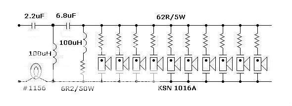
Another problem is that sometimes a cabinet with a piezo tweeter is poorly wired (for keyboards, acoustic guitar or voice) and the piezo is connected straight in parallel with the main speaker.
Problem is that the Piezo *is* a capacitor, around .15uF , and many amps do not like that load.
The proper way is to wire a resistor , often 47 ohms, in series with it, so even at high frequency the impedance is never less than that.
Wrong:

wrong:

right (the 2kHz horn already has 47 ohms inside)

right, if somewhat of an overkill:
right, although still incomplete:

see that even some "official" diagrams show the piezo straight connected, no resistor, which *some* amps can stand, but not all.
Why would it oscillate?
Lots of possibilities: there might be a ground problem, the user may have connected a mess of badly set and matched pedals in the loop, thus injecting any potential problems straight into the power amp, I have *often* seen 2 distortion pedals cascaded xP , flanger/chorus/digital pedals have high frequency clocks which may be poorly filtered and reach the output.
I was once called by some desperate customers who were playing our River Plate Stadium, 42000 people, and in the first half of the show the PA guy had to set the guitar real low and dull sounding because a cheesy FM station could be clearly heard mixed with it.
The cause of *that* problem? (which I had to solve in a darkened stage, with a flashlight held by my teeth, during a 15 minute break) was a loose jack nut in a Boss pedal which made that particular one groundless, touching the case created all kinds of synthesizer type noises.
Funny thing is that nobody suspected that particular pedal because it was "off" .
Big deal, it still was part of the grounding chain ... and failing at that.
I also remember many cases where an SS amp started getting real hot, unbearable to the touch and tripping the thermal protection, if any, with nobody playing it, or just lightly strumming some chords at low volume just to set it up.
Generally pulling pedals one by one or replacing cables solved the problem.
Another problem is that sometimes a cabinet with a piezo tweeter is poorly wired (for keyboards, acoustic guitar or voice) and the piezo is connected straight in parallel with the main speaker.
Problem is that the Piezo *is* a capacitor, around .15uF , and many amps do not like that load.
The proper way is to wire a resistor , often 47 ohms, in series with it, so even at high frequency the impedance is never less than that.
Wrong:
wrong:
right (the 2kHz horn already has 47 ohms inside)
right, if somewhat of an overkill:
right, although still incomplete:
see that even some "official" diagrams show the piezo straight connected, no resistor, which *some* amps can stand, but not all.
Title: Re: acoustic 150 zobel?
Post by: Roly on April 16, 2015, 08:34:41 AM
Post by: Roly on April 16, 2015, 08:34:41 AM
Quote from: ilyaaam i {right} to say that R404 and C404 make a zobel network across the output?
what would cause R404 to blow? my guess: amp plugged in without a load puts the output wattage across the puny 1W R404 and blows it up -
but then isnt that resistor just asking to be destroyed? ive seen one in another acoustic 150 that was blown literally in half...
Yes that is the Zobel network. Doug Self (http://www.douglas-self.com/) says it's for high and very high frequency stability (but I personally wonder if it's Elephant-Proof Paint, insurance against something that is very unlikely to happen in a guitar amp not driving piezo tweeters or a crossover?).
{
Quote from: phattIf I recall, some Acoustic rigs have Hi freq horns? If so,
What would happen if the main speaker became disconnected?
Good observation. Most likely the load would then look fairly capacitive due to the LF blocking cap in series with the pressure driver.
Perhaps you have in mind the 271;
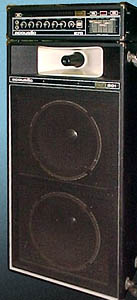
The 150 seems to have a choice of 2x12;

4x12;

or 6x12 cabs;

}
C404 going short (or full power supersonic signal from somewhere).
No. This is a solid-state amp so it looks like a battery, a voltage source with a very low internal impedance. Unlike an amp with an output transformer (e.g. valves) it makes very little difference if a load is connected or not. The supply rails dictate the highest voltage you will get on the output, say around 35-45Vpk depending on the amp rated power and load impedance. The output can even go squarewave but there is no way the voltage can go higher than the rails.
Exercise:
Taking the peak output voltage you can apply it to the Zobel at say 10kHz (a reasonable maximum for a stage amp), work out the reactance of the cap, Xc = 1/(2 Pi f C), and thus the highest current through the Zobel. You can then work out the power due to the current in the resistor.
At 0.1uF and 22 ohms/1 watt this is a pretty typical Zobel, they don't change much, maybe 0.22uF, maybe 47 ohms, but that's about it. {and as JMF says about chipamps.}
I cheated and used LTSpice. The current in the Zobel at 10kHz/35Vpk is a bit over 200mApk.
200/root(2) = Irms
200/1.414 = 141.4427157
P = I2R
(.141^2)*22 = 0.437W Well under its 1 watt rating.
Even with a lot of higher harmonics it still wouldn't be too uncomfortable at full power ('tho the power transistors might be).
Now let us assume that the cap has shorted and we just have the 22 ohm across the output.
35Vpk = 35/1.414 = 24.75247525Vrms, call it 25V
{intuitively we should estimate that a 22 ohm resistor across 24 volts is less than an ohm per volt and so is going to pass more than an amp, and an amp in 22 ohms is 22 watts.}
P = E2/R
25^2 / 22 = 28.40909091 watts. One watt resistor --> POOF!.
There are a couple of possible ways here; either your experience of these amps is a statistical outlier, or perhaps the manufacturer had a generic problem with these caps (miss-specified, faulty batch, whatever). You could "HiRel" this by using a mains-rated "X" or "Y" series yellow block cap. These are available in 0.1uF, 240VAC (630VDC test) rating, and are self-healing if they punch through due to a mains spike, just a small loss of capacitance and they don't catch fire or short.
{I might use a scrounged one in my own gear, but a new one in a client's amp.}
Perhaps this amp encountered a supersonic signal somewhere, or possibly these have a generic supersonic instability problem, possibly as the caps age. You could try putting a low level squarewave through it and see what it comes out like. If there is any stability weakness you will see it as overshoot on the edges and possibly ringing oscillations.
I also had cheesy FM radio breakthrough on a Tandy PA used at a Remembrance dawn service(!) due to speaker lead pickup and no Zobel or output inductor to stop the RF getting into the NFB loop. 0.5 ohm 5W/ww in series with the output resistor fixed.
Title: Re: acoustic 150 zobel?
Post by: gbono on April 16, 2015, 01:00:47 PM
Post by: gbono on April 16, 2015, 01:00:47 PM
I always look for simple things that can cause big problems. ;) Acoustic put a note in their 150 service manual warning that the user/musician must not use a shielded cable (especially the coiled type you don't see anymore) to connect amp to speaker caninet, because you were in jeopardy of creating a very high frequency "tuned resonant" circuit that would destroy the Z network. Check you cables.
Title: Re: acoustic 150 zobel?
Post by: phatt on April 17, 2015, 07:56:36 AM
Post by: phatt on April 17, 2015, 07:56:36 AM
Quote from: gbono on April 16, 2015, 01:00:47 PM
I always look for simple things that can cause big problems. ;) Acoustic put a note in their 150 service manual warning that the user/musician must not use a shielded cable (especially the coiled type you don't see anymore) to connect amp to speaker caninet, because you were in jeopardy of creating a very high frequency "tuned resonant" circuit that would destroy the Z network. Check you cables.
Good point :dbtu:
why yes I still often run into well seasoned players (old buggers like me ;)) who still don't realize the danger of using coax for speaker cable.
Phil
Title: Re: acoustic 150 zobel?
Post by: ilyaa on April 20, 2015, 01:54:49 PM
Post by: ilyaa on April 20, 2015, 01:54:49 PM
whether or not it was something simple is not, unfortunately, for me to tell - i bought this amp at a swap meet as a fixer-upper -
replaced the zobel -
looks like things are working OK but there is definitely an oscillation - a square wave in the input looks bad at the output - sharp overshoots on the edges. and a sine wave looks wobbly and double-vision.
any strategies for tracking down this kind of problem, aside from trying to isolate whether its pre- or power-amp?
Title: Re: acoustic 150 zobel?
Post by: J M Fahey on April 20, 2015, 10:30:36 PM
Post by: J M Fahey on April 20, 2015, 10:30:36 PM
Quote from: ilyaa on April 20, 2015, 01:54:49 PMNone of that shows an oscillation ... at all .
looks like things are working OK but there is definitely an oscillation - a square wave in the input looks bad at the output - sharp overshoots on the edges. and a sine wave looks wobbly and double-vision.......... any strategies for tracking down this kind of problem, aside from trying to isolate whether its pre- or power-amp?
Scope screen reading 101:
* square wave with sharp overshoot?: treble/bright boost in the amp .... very very normal in a Guitar amp.
* wobbly and double-vision sinewave?: the sinewave is perfect, you are having a sync problem in your scope.
What frequencies are we talking about anyway?
Title: Re: acoustic 150 zobel?
Post by: Roly on April 21, 2015, 03:38:18 PM
Post by: Roly on April 21, 2015, 03:38:18 PM
Square wave test - caution: (I should have said) if fed through the preamp the EQ will have a profound effect on waveshape, therefore this test is really only meaningful when applied to the power amp alone (e.g. via Fx Return).
My first thought also.
Your enemy;

The lower trace is showing bursts of high frequency parasitic oscillation on a signal. Unlike straight supersonic oscillation parasitic oscillations only occur under certain circuit conditions of drive and load, the circuit is said to be only conditionally stable, and this is the implication of the Acoustic caution mentioned by gbono above. Ideally all amplifiers should be UN-conditionally stable under all load and signal conditions.
Using a square rather than sine wave is poking a stick down its hole, a serious provocation for an instability to show itself. The sharp edge of the square wave is an electronic version of giving it a whack on the case. If anything is going to ping, ring, or burst into HF oscillation, that's when it is going to be "shocked" into doing it.
I've encountered the very occasional roasted Zobel, but apart from obvious stuff like the cap shorted, it's hard to tell what conditions may have caused the failure since they always seem to be situational, unreported to me (e.g. using a curly cord for the speaker), and no other fault can later be found in the amp. I've had amps in for other repairs where the Zobel must have been burned out years before (e.g. fluff accumulating on the burnt resistor), the cause lost in the mists of time, and perhaps multiple ownership.
Most times a bit of detective work will develop a reasonable explanation for a fault, (e.g. one of the speaker leads has an intermittent short), but there are also a small percentage of repairs where is is not obvious from the equipment and there is a lack of other information.
{I'm reminded of a multi-headphone amp from a studio with one output seriously fried. The only thing I could say for sure is that there wasn't enough power available within the unit to cause that much damage, so the power had apparently come in via the headphone socket. I can only guess that somebody accidentally plugged an amp speaker lead into the headphone output (both 6.5mm) and gave their amp a thrash. It certainly isn't the first time I've seen damage from that mistake. For a conscientious repairer a guess, even a good one, isn't very satisfactory because it's nice to be certain, but without somebody putting their hand up it had to remain a mystery.}
Quote from: J M Fahey* wobbly and double-vision sinewave?: the sinewave is perfect, you are having a sync problem in your scope.
My first thought also.
Your enemy;
The lower trace is showing bursts of high frequency parasitic oscillation on a signal. Unlike straight supersonic oscillation parasitic oscillations only occur under certain circuit conditions of drive and load, the circuit is said to be only conditionally stable, and this is the implication of the Acoustic caution mentioned by gbono above. Ideally all amplifiers should be UN-conditionally stable under all load and signal conditions.
Using a square rather than sine wave is poking a stick down its hole, a serious provocation for an instability to show itself. The sharp edge of the square wave is an electronic version of giving it a whack on the case. If anything is going to ping, ring, or burst into HF oscillation, that's when it is going to be "shocked" into doing it.
I've encountered the very occasional roasted Zobel, but apart from obvious stuff like the cap shorted, it's hard to tell what conditions may have caused the failure since they always seem to be situational, unreported to me (e.g. using a curly cord for the speaker), and no other fault can later be found in the amp. I've had amps in for other repairs where the Zobel must have been burned out years before (e.g. fluff accumulating on the burnt resistor), the cause lost in the mists of time, and perhaps multiple ownership.
Most times a bit of detective work will develop a reasonable explanation for a fault, (e.g. one of the speaker leads has an intermittent short), but there are also a small percentage of repairs where is is not obvious from the equipment and there is a lack of other information.
{I'm reminded of a multi-headphone amp from a studio with one output seriously fried. The only thing I could say for sure is that there wasn't enough power available within the unit to cause that much damage, so the power had apparently come in via the headphone socket. I can only guess that somebody accidentally plugged an amp speaker lead into the headphone output (both 6.5mm) and gave their amp a thrash. It certainly isn't the first time I've seen damage from that mistake. For a conscientious repairer a guess, even a good one, isn't very satisfactory because it's nice to be certain, but without somebody putting their hand up it had to remain a mystery.}
Title: Re: acoustic 150 zobel?
Post by: ilyaa on April 22, 2015, 09:01:07 PM
Post by: ilyaa on April 22, 2015, 09:01:07 PM
hmmmm ill do some more snooping -
the zobel cap was only rated for 100VDC, so maybe a mains spike shorted it?
the zobel cap was only rated for 100VDC, so maybe a mains spike shorted it?
Title: Re: acoustic 150 zobel?
Post by: Enzo on April 22, 2015, 10:31:31 PM
Post by: Enzo on April 22, 2015, 10:31:31 PM
It may be shorted but that is not likely why. Anything on the mains that could do that would have damaged a bunch of other things too. To get to that cap, a mains spike would have had to make it all the way through the power supply, and then down through the + side outputs to get to the amp output bus, THEN through the resistor to zap that cap.
Title: Re: acoustic 150 zobel?
Post by: Roly on April 23, 2015, 07:36:46 AM
Post by: Roly on April 23, 2015, 07:36:46 AM
Yep.
Maybe it just decided that it was mad as hell and wasn't gonna take it any more. :lmao:
{'course if you are feeling lucky you could try to re-create the fault conditions. Repair the Zobel, hook your CRO on the output, and connect the amp to its speaker via a long curly cord, and hold on to your hat. 8| }
Title: Re: acoustic 150 zobel?
Post by: ilyaa on May 22, 2015, 12:38:21 PM
Post by: ilyaa on May 22, 2015, 12:38:21 PM
kay back to this guy -
zobel network replaced -
open thermistor in output transistor bias network replaced -
still a bad hum when amp is on -
measured at speaker terminals, i get about 20VDC - it seems to go up and down when the amp is turned on/off, but definitely DC there -
whats the most likely suspect? the huge output coupling cap?
Title: Re: acoustic 150 zobel?
Post by: Enzo on May 22, 2015, 02:15:43 PM
Post by: Enzo on May 22, 2015, 02:15:43 PM
Well, look on the amp side of the speaker cap. This is a single supply amp, schematic says +75v, and it also says about 37v on the amp side of that cap. No signal, no load, just powered on at idle, what is the DC voltage there. If it is within a couple volts of half the power supply, then it sits about right.
You measured 20v DC on the speaker itself? Or at the speaker terminals but no speaker connected? With no speaker or load, ther is no way for that cap to charge. In which case, slap something like a 100 ohm resistor across the output just to give the cap a chance to charge. Does that DC settle down with 100 ohms? (100-200-whatever, value not important)
You measured 20v DC on the speaker itself? Or at the speaker terminals but no speaker connected? With no speaker or load, ther is no way for that cap to charge. In which case, slap something like a 100 ohm resistor across the output just to give the cap a chance to charge. Does that DC settle down with 100 ohms? (100-200-whatever, value not important)
Title: Re: acoustic 150 zobel?
Post by: gbono on May 22, 2015, 07:52:25 PM
Post by: gbono on May 22, 2015, 07:52:25 PM
Did you check the power supply? I have seen the filter capacitor fail on these amplifiers - had one so dried up you could shake the capacitor and hear a rattle. There is a 1000uF/50V? aluminum electrolytic on the output that should be checked.
Title: Re: acoustic 150 zobel?
Post by: ilyaa on May 24, 2015, 01:12:51 PM
Post by: ilyaa on May 24, 2015, 01:12:51 PM
whoops!
20V ripple on the positive rails!
replace filter cap??
http://www.electronicsurplus.com/sprague-36d392g075bb2a-capacitor-electrolytic-3900uf-75vdc - this one look ok?
20V ripple on the positive rails!
replace filter cap??
http://www.electronicsurplus.com/sprague-36d392g075bb2a-capacitor-electrolytic-3900uf-75vdc - this one look ok?
Title: Re: acoustic 150 zobel?
Post by: Enzo on May 24, 2015, 03:53:24 PM
Post by: Enzo on May 24, 2015, 03:53:24 PM
I don't see the power supply portion of the schematic. But assuming 3900uf/75v is what you want, looking at the description of the cap you linked, it appears to have a 1979 date code. Almost as old as the cap in there now, plus they want $20 for it. That is a lot for a cap almost 40 years old.
Since it is a 75v supply, I'd like to see at least a few more volts rating on the cap. The originals used those huge screw terminal caps. A look at Mouser showed me a 3900uf 75v cap for $48. But looking at 3900uf 100v, I see a screw terminal cap for $19.73. And that would have a current date code, not one from 1979. But the reason they used the huge screw terminal caps is that was what was available back them. But if we look at other forms, there are snap-in style caps in 3900uf at 80v and at 100v either one in stack and available for under $5. To save $15, I'd find a way to mount the snap-in.
Since it is a 75v supply, I'd like to see at least a few more volts rating on the cap. The originals used those huge screw terminal caps. A look at Mouser showed me a 3900uf 75v cap for $48. But looking at 3900uf 100v, I see a screw terminal cap for $19.73. And that would have a current date code, not one from 1979. But the reason they used the huge screw terminal caps is that was what was available back them. But if we look at other forms, there are snap-in style caps in 3900uf at 80v and at 100v either one in stack and available for under $5. To save $15, I'd find a way to mount the snap-in.
Title: Re: acoustic 150 zobel?
Post by: ilyaa on May 24, 2015, 04:00:02 PM
Post by: ilyaa on May 24, 2015, 04:00:02 PM
whoa good catch!! wheres the date code?
the power supply is in the file i attached in my first post -
its a 80V cap - i thought a few volts headroom was a good idea, too - ill check the mouser part!
the power supply is in the file i attached in my first post -
its a 80V cap - i thought a few volts headroom was a good idea, too - ill check the mouser part!
Title: Re: acoustic 150 zobel?
Post by: Enzo on May 24, 2015, 09:15:20 PM
Post by: Enzo on May 24, 2015, 09:15:20 PM
The 66C7917 looks like a date code to me, 17th week of 1979. I could be mistaken, of course. But new or old, you can save some dough by using a more common form factor. The circuit only cares about the specs, not what the cap looks like.
Title: Re: acoustic 150 zobel?
Post by: ilyaa on May 25, 2015, 04:01:39 AM
Post by: ilyaa on May 25, 2015, 04:01:39 AM
hmhmhm
upon final inspection, i'm seeing 20VAC ripple on the 37V rails/on EITHER side of the OUTPUT cap -
output cap to blame? easier to replace, too, phew
upon final inspection, i'm seeing 20VAC ripple on the 37V rails/on EITHER side of the OUTPUT cap -
output cap to blame? easier to replace, too, phew
Title: Re: acoustic 150 zobel?
Post by: J M Fahey on May 25, 2015, 05:14:52 AM
Post by: J M Fahey on May 25, 2015, 05:14:52 AM
Quote from: ilyaa on May 25, 2015, 04:01:39 AM1) earlier you said you found 20VDC on "both sides of the output cap" ...what will it be?
hmhmhm
upon final inspection, i'm seeing 20VAC ripple on the 37V rails/on EITHER side of the OUTPUT cap -
output cap to blame? easier to replace, too, phew
2) *if* you found 20VAC on what you call the 37V rail (which is not a power supply rail but the speaker out) then you must hear a deafening hum through the speaker.
100W RMS of it.
3) *if* it's AC after all, then it's normal finding it on both ends of a *good* coupling cap, that's their job.
Title: Re: acoustic 150 zobel?
Post by: ilyaa on May 25, 2015, 12:12:58 PM
Post by: ilyaa on May 25, 2015, 12:12:58 PM
with a scope and the amp unloaded:
there is normal small ripple on the main filter cap as well as on the 75V power rails
there is a big 120hZ 20VAC ripple on the speaker out (37V rails) -
i do measure some DC on the speaker out as well (but that's with no load plugged in - maybe thats the output cap charging through the zobel network?)
there is a loud hum when amp is plugged in, but not 100W loud
maybe C309 or C310 in the power amp...
...
Title: Re: acoustic 150 zobel?
Post by: Enzo on May 25, 2015, 02:41:44 PM
Post by: Enzo on May 25, 2015, 02:41:44 PM
C309/310 will not make hum.
You are scoping? Then look at the driver collector Q302, it drives the primary of the drive transformer. Is there a large AC signal there? If so, then of course the output would have it too. Look at the +40v that powers Q302 at its emitter, and decoupled by C307, is that clean and close to voltage?
Pins C,D of the power amp module have the input signal. Is there a hum signal there? What if you grounded the negative end of C301, where those input signals meet, does that kill the hum. That would tell us hum was before or after C301. In fact, that small electtrolytic C301 is suspect in my view, even if it isn;t the immediate problem, in my experience, those small lytics from that era are very often flaky.
Title: Re: acoustic 150 zobel?
Post by: ilyaa on May 25, 2015, 05:43:12 PM
Post by: ilyaa on May 25, 2015, 05:43:12 PM
q302 looks fine/voltages clean
hum appears after R310/C308....
sure it cant be c309?
hum appears after R310/C308....
sure it cant be c309?
Title: Re: acoustic 150 zobel?
Post by: ilyaa on May 29, 2015, 09:18:45 PM
Post by: ilyaa on May 29, 2015, 09:18:45 PM
Replaced output cap and ripple is down!
We're still humming, tho....I'm just gonna recap whole power amp see if that does it
For the output cap, should I be concerned with any other parameters other than voltage? Wondering if it has to be really beefy...
We're still humming, tho....I'm just gonna recap whole power amp see if that does it
For the output cap, should I be concerned with any other parameters other than voltage? Wondering if it has to be really beefy...
Title: Re: acoustic 150 zobel?
Post by: Enzo on May 30, 2015, 01:50:07 AM
Post by: Enzo on May 30, 2015, 01:50:07 AM
Just use what the schematic calls for. 1000uf, but if it were mine I would bump the voltage from 50 up to 80 just for good practice. I forget, but if it is a can cap with screw terminals, it is not necessary to get the same type. A plain old cap with wire leads will be fine, just mount it securely. Low ESR would be good, but I doubt you will find high ESR caps advertised.
How much ripple is on the main 75v supply? The hum you are hearing, have you determined if it is 60Hz or 120Hz? 120Hz hum is from power supply ripple, which could be lack of filtration but could also be due to ripple currents sharing ground path with other circuits. 60Hz hum does not come from filter caps.
How much ripple is on the main 75v supply? The hum you are hearing, have you determined if it is 60Hz or 120Hz? 120Hz hum is from power supply ripple, which could be lack of filtration but could also be due to ripple currents sharing ground path with other circuits. 60Hz hum does not come from filter caps.
Title: Re: acoustic 150 zobel?
Post by: ilyaa on June 01, 2015, 11:40:55 AM
Post by: ilyaa on June 01, 2015, 11:40:55 AM
k recapped power amp and hum is gone - still a bit noisy but preamp probably needs a recap, too!
otherwise, amp sounds great!
it was 120hZ hum - and it was originally about 20 Vp-p and went down to about 1-2Vp-p
not sure if a single cap was to blame - i got a bit impatient, i have to say, so i just recapped whole thing (but left original power supply filter cap - that would probably help, too, but for my purposes wasnt necessary) and seemed to do the trick!
thanks, guys!