Menu

Show posts

This section allows you to view all posts made by this member. Note that you can only see posts made in areas you currently have access to.

Show posts Menu

Messages - J M Fahey

#91
Schematics and Layouts / Re: Marshall 2201 ...
May 26, 2017, 10:34:53 PM
The schematic posted above does not show the power supply or transformer, so it does not help on that.
*Some* marshalls had voltage selectors, some had not; so plan B is to look at the back panel and see whati it shows.

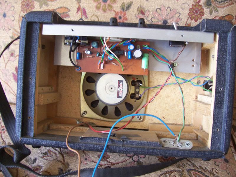
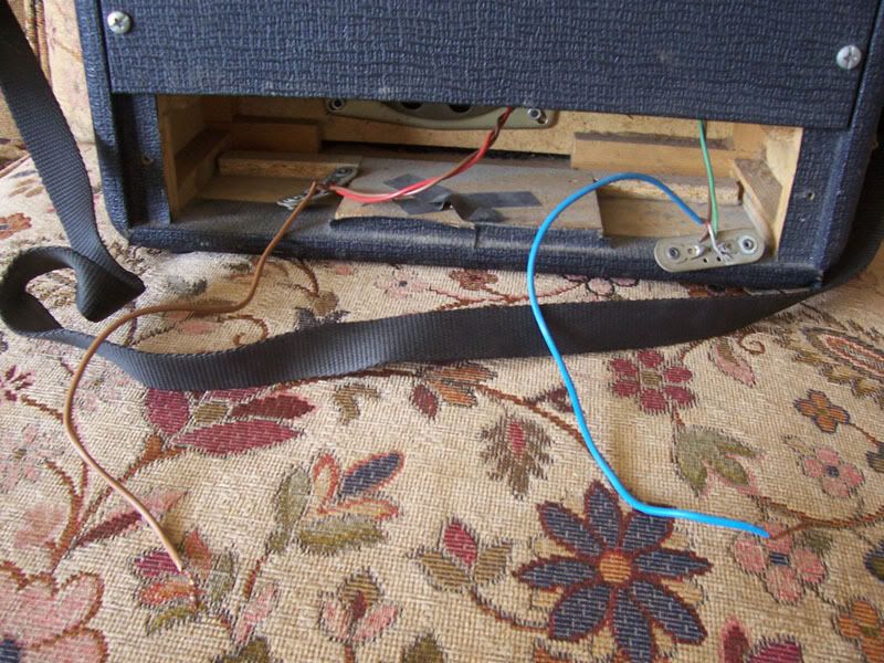
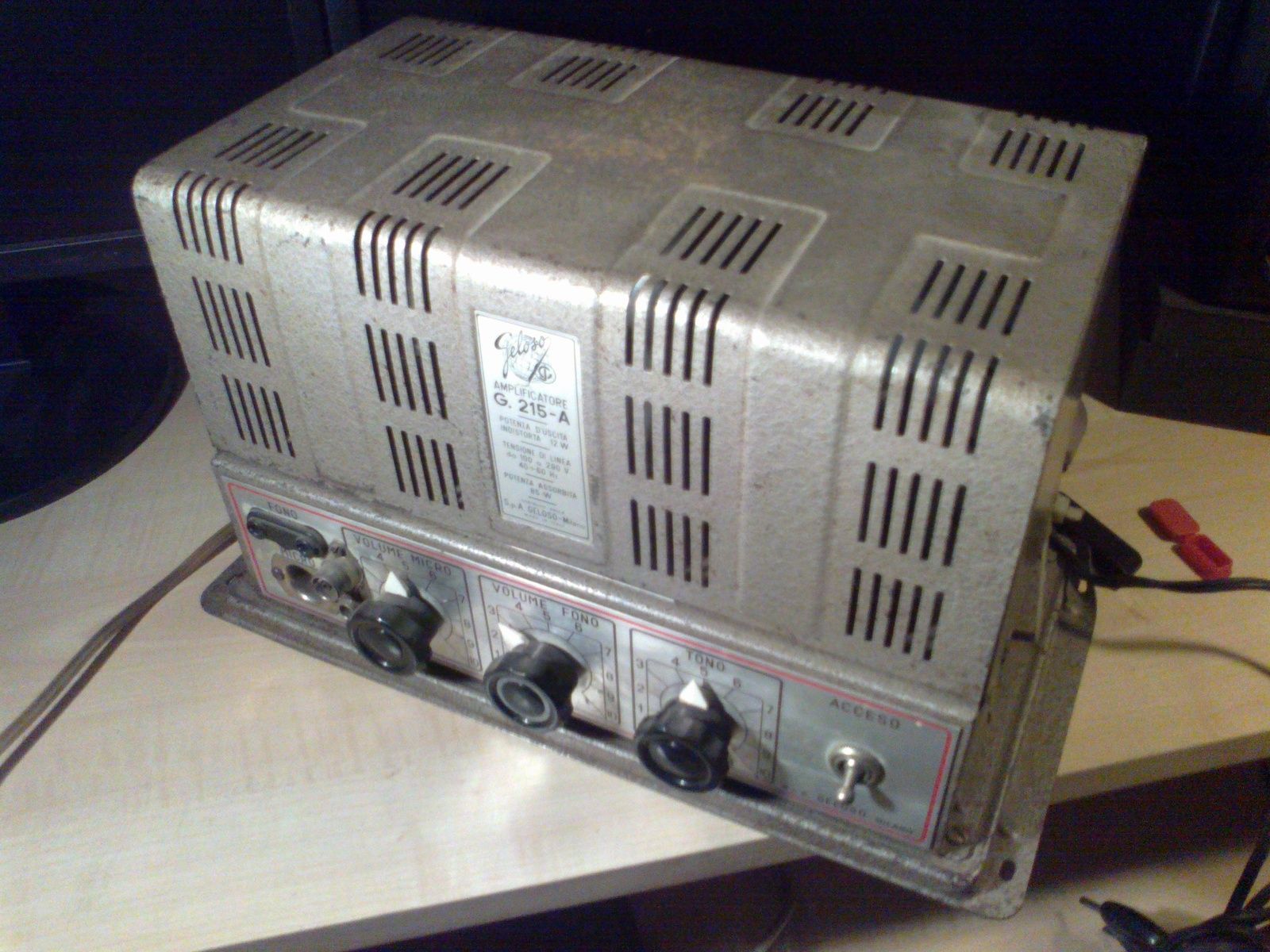
If not clear, take a good gut picture showing power socket wires, fuse holder, switch, and transformer wires, we might see something.

Not sure what you call "220V American power", usual mains voltage available at home outlets is 120V ; although 240V are often available "inside the wall"  they are only connected to special sockets for high power appliances, such as large air conditioners, large washing machines, some ovens, etc.
#92
Tubes and Hybrids / Re: Noisy pots
May 26, 2017, 11:27:09 AM
1) starting from the end: please do post the schematic, we always love to see weird ways to do things
2) that 4M7 grid resistor most certainly means the first tube is grid leak biased.
Grid leak meaning exactly that: some electrons are catched by the grid, turning it negative and providing "free"  bias  :o
Now if you let the grid free float it does not provide a voltage reference relative to cathode (which is what matters) and plate current wanders all over the place because actual bias floats all over the place.
And if grid to ground resistor is way too low it sucks those electrons down and bias disappears; I bet some brave soul found hatbby using a high but defined resistor there bias voltage is quite stable; you will find 5M to 10M resistors there, maybe the odd 3M3, hardly any lower.
Of course, this is a real and measurable DC voltage; if it interacts with a guitar pot it *will*  scratch  :o
If the amp is old enough, (say 40`s or 50`s) normal cheap microphone was a high impedance crystal one, and normal phono pickup was again a high impedance, very high output crystal powered too.
Those might provide up to 1V RMS output, a few 1.5V  :o

Those were basically flat, and old records were only lightly compensated, nothing like bass heavy treble shy RIAA which came later, and at the beginning was a "Hi Fi guys"  only technology.

I started working on this in 1968 and some early jobs (which seasoned Pros would reject as worthless of repair) were by then old (do the Math) small town dancing Clubs, old School/Church PA systems, etc.
Think your Bogen and similar PA amps, and invariably consisted of a squarish chassis, with 2 EL34 (we are quite European minded and 6L6 were unused and practically unknown) , driven by a couple octals in the older ones, or miniature 8 pin (not a typo) Philips "A technique" tubes, or the odd EF86.
Front panel showed a Mic Volume pot, for the announcer and/or singer (orchestras were unamplified), a Phono input for "selected recordings" played by the Stone Age DJ ancestor, sometimes a single knob Tone control, .... and nothing else.


People hated those amps because all were poorly maintained, hummed/buzzed (you could always tell whether the PA was ON or OFF  ::) ) and when they came for repair they not only distorted a lot (that was almost acceptable) but chopped audio to the point of being fully unusable.

Typical problem was that leaky paper in oil caps leaked horribly (both electrically and actually dripping oil) and misbiased the next stage.
A 12AX7 triode (6AV6 was very popuar and it´s "1/2 of a 12AX7") with, say, +5V on its grid becomes saturated all the time and chops audio going through it, only allowing highest peaks through.
#93
Amplifier Discussion / Re: Great little amp!
May 26, 2017, 10:50:40 AM
Not only me :)  , joecool is an early fan and always uses his  :dbtu:
#94
Pity nobody scanned and posted the last chapters showing a lot of yummy schematics.

Flawed logic behind that is "all schematics are in the Net anyway"  which of course is not true.

Classic Fender Tube schematics and layouts are easily available, of course,  a few Tube Gibson ones too, practically no SS one shown there can be found, so in fact it would be great if somebody scanned and posted his own copy in full.

Sadly the Net is dominated by tubeheads, where anything tube, no matter how poor, must be kept, while early SS amps, some very clever or unique, are lost.

Oh well.
#95
Post a couple pictures of the one you have today.

IF you get a TBA810 then you may clone the original PCB  :o

You can scan it , import photographic image into a graphics program such as Corel Draw, Autocad  :o or free open source one (is it inkscape?) and redraw it black on white to get proper artwork without need to install and learn some PCB software.

Or do it the old way which I used for decades: I´d simply tape some semi transparent transparent paper on the solder side, and hand trace it using a drafting pen and China/India/technical drawing  ink.
Then use that to make a PCB , even by hand.

If not you can build same preamp and a TDA2030 power amp (will sound exactly the same) on perfboard, last night I checked and TBA810 was set up to have gain about 50X , easy to do with TDA2030

In fact I liked this project and in a near future might design a PCB for it and make a few.
#96
Yes, you can basically clone it.
The original power integrated circuit (TBA810) is obsolete and unavailable but no big deal, you can replace it with a current TDA2030, I can give you the new values, and you can build it on perfboard.
A 12V 1A transformer is enough to power it.


this is the battery only version, same as above without the power supply.
In fact you can power it with a surplus 18-20V Notebook supply, go figure.


Nice project for galaxiex ... although he will *insist*  on the original unavailable IC ;)
#97
Just checked wired amp price , today:
Quote$432.00 in 1968 had the same buying power as $3,076.66 in 2017

Annual inflation over this period was about 4.09%

Apply same 7.12 : 1 correction factor to speaker cabinets.

In fact real Inflation value is quite higher, for various reasons, from Political to Technological , so updated price would have been even higher than calculated.
#99
Amplifier Discussion / Re: Great little amp!
May 07, 2017, 02:18:38 AM
Killer little amps.
Sound **GOOOOODDDDD****
#100
Thanks Toadmeister :)   :dbtu:
#101
Ok.  I see no 2A fuses whatsoever on the schematic.

The main supply ones F21/F22 on the secondary side are either 5A for the 100W version, or 10A (indicated by a number 8 inside a triangle)  for the 200W one.

On the primary mains/220V side, regular Lab L5 does not use plain "thin wire inside a glass tube"  fuses but resettable "circuit breakers" , miniature versions of what´s currently used on home electrical panels.

That said, *maybe*  original USA made circuit breakers were not type approved under strict German Electrical Safety rules and they opted to use plain fuses instead, so please check what goes through those fuses.

Now that I think about it, Euro rules demand "fuses on all transformer windings", those *might* have been added on the low voltage supply (+/-25V raw, +/-15V regulated).
Missing one would certainly make amp soound funny, but please check what they connect to first.
#102
Ok, welcome to the Forum :)

1) please search for the full Gibson Lab L5 amplifier schematic, it might even be inside SSGuitar , and post it here, so we all talk the same.

2) don´t know what your fuse connects to, let´s wait for the schematic, but your picture shows *one*  red circled empty holder, yet there is another empty one on top of it. ??????

3) where are you from? What is your mains voltage?
Is the amp plugged straight in the wall or does it use a transformer?

4) after we sort this fuse problem, maybe you might try to record and post that "strange sound"  :)
#103
The Newcomer's Forum / Re: Strange amp in a suitcase
April 27, 2017, 01:42:47 AM
Have you checked you have NO DC at that jack?

Where/what/how is it connected to?
#104
QuoteHowever, the circuit documentation still describes the associated circuit as a crude short circuit protection scheme.
Well, that´s what it originally was.
And not *that*  crude, in its original implementation it was functionally the same as the standard current clamping protection with diodes or transistors.
Way back then, we knew it as "the RCA protection" .
FWIW, found in transformer driven SS amps.
The original idea was never to increase output impedance; amp was standard high damping type, as expected in a Hi Fi amplifier, and started limiting current only above a certain preset (dangerous) level.
Will search for some old schematics ... printed on paper of course ;)  , no Internet way back then :O
#105
Cool  :dbtu:

In a nutshell: I think the amp "as original"  is just on the edge, too close for comfort, to drive 4 ohm loads.

Not that it can´t absolutely drive them, otherwise they would not have released them, but real world touring or even plain stage use (LOUD, matching a LOUD drummer) are hard on an amp.

I guess that you can add 2 more extra devices or replace the current ones with double chip Exicons, which work very well.

Whenever possible show us what´s making it tick :)