Menu

Show posts

This section allows you to view all posts made by this member. Note that you can only see posts made in areas you currently have access to.

Show posts Menu

Messages - dimkasta

#1
To be fair, the 18W are peak to peak. The RMS rating should be closer to 10W, and is probably further limited by the small transformer, the small power bank and the distance/inductance from the power bank to the chip itself.

TBH, by just removing the leds and adding an external 12" cab, you already have a decent amp  if you have a good set of pedals to complement and keep your expectations realistic.

For gigs I would probably consider it only if you are very budget constrained, and then I would mic it to avoid overheating the chip.

Unfortunately I cannot provide samples since my p10 is now just an empty chassis for experimenting with other circuits.
#2
Slow day at work today, so I had some time to experiment.

There are two interesting parts in the first gain stage.

The first is the capacitor C5 and how it interacts with the gain pot. At first glance it looks like a coupling cap. But it's in the feedback loop, and interacts with the pot. As the gain increases, the upper part of the pot divider decreases, and the cut off frequency of the high pass filter is increased (less bass passes the filter). But because the filter is in the negative feedback loop, this means that low frequencies are increased at the output. This works exactly like a resonance control. But the problem is that bass increases with gain. Which is quite counter intuitive, especially at higher gains, unless you like fuzzy distortion. Removing C5 removes that weird interaction and high gain sounds tighter.

The second area is C4, R4, R5 and the switch. The switch acts exactly like turning up a presence control at high gain. R4 sets a minimum resistance so that things do not go too far. Ideally, we would replace R5 with a 100K or 50K pot wired as a variable resistor, and then remove this pole of the switch so that we have full control both at high and low gain. This would give us a very versatile presence-like control.
#3
Short update about my progress. I am currently going too far. I have designed my own PCBs and face plate. I will probably open a new thread when I have some more to show. Unfortunately PCB fabrication takes too long and design changes hurt both in time and money

Just a teaser for now

You cannot view this attachment.

You cannot view this attachment. 
#4
Hehe

Yeah that's from the same company that released the mini Friedman BE, the mini Bogner and the mini Diezel VH. Soldano just probably tweaked the voicing.

I am also curious about its preamp. The power amp is 100% some chip.
#5
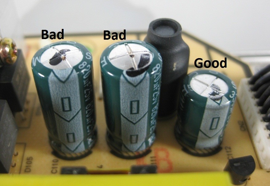
Yes electrolytic caps definitely age. But it's hard to say how much life exactly you can expect from them. It depends both on the usage, but also on the storage conditions and their quality. 20+ years is the point where I would start worrying. A quick way to get rid of duds is to see if their case is bulging or leaking.

A quick sample from the internet


I would still worry though. Even if they have no visual problems, they can still be duds. A safer way is to test them with a multimeter or even better an LCR or ESR meter.

You mention wimas. These are probably film and these age in a much much much slower rate. The most usual problem with them is oxidization of the wires (which can be solved with some sandpaper)
#6
Courtesy of the nice folks at diyaudio

I don't know how feasible the 36R is, but here are some alternate values that can be used for the same curve

You cannot view this attachment.
#7
Yeah I just did the change and the character did not change at all (I already had removed C12)

Again, this mod is about removing gain from the third stage, making it a buffer

So I removed R15, R16, R17, C12 and C13, and then bridged R15 and R17 so that pins 1 and 2 of the opamp are connected.

The volume is now much more easy to control for home use. I can even get some overdrive from the first stage (sounds meh) and I can keep it on civil levels, something that I could not do before. It can still get loud if you max it, but it will be much more civil.

This mod also probably makes the change of P4 to audio taper irrelevant

Keep in mind that the overall volume will be lower than previously, since I plan to increase the overall output of the 2 first stages, but have not done it yet.

If you use your p10 on loud occasions, do not do this mod yet.
#8
Some more work on the boring parts of the gain structure

The power stage is a TDA2030A that runs at +-20V and with an 8ohm speaker gives 18W of power. This means 12V p2p at the speaker. And since the chip is running at 13x gain or 22dB, the max input before it clips is ~900mV. For stability and simplicity, I will avoid messing with the power section.

The tone stack is also a given quantity.
If you use stock values, there is a min attenuation of 6dB or 1.99x
If you use my changed values, there is a min attenuation of 9dB or 2.81x

This is the step that kinda defines our gain requirements for the third opamp stage.

We need max ~900mV

So to get max power, we need before the stack:
0.9 x 1.99 = 1.791V for the stock stack and
0.9 x 2.81 = 2.529V for the modified stack

These numbers are already easy to get from the two first opamp stages, and they are nicely placed in a level where we can also hard clip them near their value with various diode combinations if we want. And even get their hard clipping even at max power, while protecting the power stage from clipping the chip.

So in both cases, the 3rd opamp stage can be safely converted into a buffer. We do not really need its gain.

The extra benefit, we avoid further amplifying noise from the previous stages or introducing more.

And we should get much more home-friendly volume control, without losing max power.

So my next mod to test is removing R16, C13, C12, R15 and R17, and bridge the pads of R15 and R17 with some wire.

Note that this means an attenuation of max ~6.5x or 16dB from previous volume settings. It might feel like pushing the gas pedal and not getting enough speed. Max speed will be still the same though.
#9
Some thoughts on voltages and gain structure.

At this point, my amp is super clean with huge headroom. And effectively it's a 18W amp, since the TDA is working at +-20V at x13 gain, and the unrestricted preamp can saturate it easily even on low gain. This is LOUD.

A first observation is that by increasing the gain past 1 o'clock, the amp gets increasingly darker and even muddy. Something that was more evident when I tried increasing R8 to 100K and 200K to increase the clean gain. There seems to be some compensation by C8 being out of the loop when the high gain button is pressed, resulting in an additional highpass filter. In low gain setting, the cap is in the loop so the opamp compensates for its effect.

This complicates how the gain structure works. And makes it more difficult to rework the thing if we want to add some decent sounding overdrive or distortion. Especially for home volumes, since there is not enough signal level to clip even low-voltage-drop diodes. I will have to see this as a chain eventually.

A first thought is to keep clipping and overdriving between the two first opamp stages and eliminate the overdrive button. And perhaps move it to control the gain of the TDA or of the last opamp stage. The TDA is not stable below 20db. And it will be difficult to further reduce the gain without changing it to something like LM1875.. Which might be a good idea anyway. C12 is already gone, so we could perhaps control the gain at this stage as well, without too much effort. So that we could use low output for home and boost it when we play with others and we need the full 18W.

Next we would have to perhaps decrease the voltage level of the preamp. So that bigger gain is still home-friendly and enough to bring either the opamps close to saturation/overdriving each other or enough to clip diodes. 9V sounds reasonable and we should be able to transfer some pedal tech easily.

The first thing I checked was R27 and R28. To have a voltage drop of 7V across them, this means that the entire thing is current limited to ~8.5mA. Which looks rather marginal to operate the two 4558 including losses. If we want to go to 9V output, we would have to make them 1K8, which would bring the current to 6mA, which sounds even more restricting. I will have to do some testing and measuring to see how this would work, but I think that some regulators would work better here. They might remove some character since the thing uses the impedance of the preamp to form the voltage. I don't know how significant this is going to be, but probably not enough since opamps should have enough PSRR.

Any thoughts?
#10
OK I have tried the modified tone stack from the other thread.
Without messing with the output of the previous stage and the loading of the next, this gives  a curve that is spot on to the classic VOX. The pots do not track the same, but it's close enough.

More explanation here
https://www.ssguitar.com/index.php?topic=5153.0

What I did was replace the following

R10 - 15K
R11 - Removed and added a wire from its C11 pad, towards the junction between R12 and P3-pin3
R12 - 1K
C9  - 1nF
C10 - 560nF
C11 - 150nF

You cannot view this attachment.

The result was spectacular, especially in the clarity of the amp and the highs.

Just be careful with the PCB. It's very crappy and it's very easy to lift pads if you overdo it. If you do not have a proper soldering tool, then perhaps it would be easier to cut the parts and then solder the new ones point to point on top of the potentiometers. Especially if you plan to experiment with different parts.
#11
I am working on this as part of my other P10 thread, but I thought this deserved its own discussion.

I used the Tone Stack Calculator application to plot the frequency response of the tone stack, and compare it to those of Pathfinder 15r and an old school VOX stack. And then try to find values that could work and give a similar curve.

I do not know much about filters and plotting curves, so I would appreciate any feedback

This is the plot of a classic VOX. I tried different schematics like that of AC15c1, but the curve was very close to this one.

You cannot view this attachment.

This is the stock pathfinder 10. The bass pot is a bit off to compensate for the extra resistor in the circuit. And yeah it's quite off...

You cannot view this attachment. 

This is pathfinder 15r. Still a bit off, but much better

You cannot view this attachment.

This is what I am planning to do on my pathfinder 10. I tweaked it to come as close to the classic Cox curve with values that I have. I plan to do this point to point on top of the pots. I know that the pots won't track the same as the original, and the curves won't be identical, but the starting point should be close enough to give a good approximation
R4 will be replaced with a single resistor. That's why it's shown at 100%.


You cannot view this attachment.


Any thoughts? Did I miss something?


#12
After one year, I finally found some time to add the unbuffered FX loop.

It's basically two quarter inch switching sockets.

I did not take a photo and I am a bit bored now, but you can see how it works on my Champion 40.

The right one gets the signal from the preamp, and the left one returns it to the power amp. You can use both independently. And with nothing connected, the thing defaults to pass the preamp to the power amp.


I have not managed to play with it a lot yet. I will post more (including photos) when I have some more time.
#13
Sorry everyone I was super busy and did not have much time to play. But we have lots of progress this weekend.

Here is what I did

You cannot view this attachment.

I added two switching quarter inch sockets. The right one can be used to get the signal from the DSP, and the left one to feed the signal to the power stage. Of course you can use them separately as you want. And with nothing connected, the thing defaults to feeding the DSP to the amp.

So this works like an unbuffered simple FX loop. Keep in mind that both the DSP and the power amp are connected to the ground, so you might have to fix ground loops. I only tried this with a battery powered pedal.

The main culprit for the hiss unfortunately is the DSP pcb. I do not know if it comes from the PSU or from the design itself, or from the buffer stages (yet). There is still some noise on the power stage, but it's significantly lower, and for me it was lower than the noise from my guitars.

Testing the power amp with my mojomojo in the middle like a buffered volume, I was surprised how much better the speaker was behaving. It is now ringing loudly and with much authority. Which further points that the output stages of the DSP are also probably weak.
And of course, the volume is now much more manageable for home-use

I do not know how I will proceed. I will play a bit more with it using my preamp pedals and see how it goes. It was already working nicely as a plain cab (for example with my VOX pathfinder 10). But it's power amp is powerful and behaves nicely even at low volumes. At this point I think that its best bet is to work like a powered cab for pedals.

Here is the mod list updated and re-ordered

[] Add a 1/4 jack/plug so that I can reuse it as a cab
[] Add an unbuffered FX loop. This was huge with a pedal as a powered volume. It's surprising this way, and it might even make sense to use as a powered cabin.
[ ?? ] Prepare for replacement preamps or something for when the DSP goes to the big gig in the sky. Again, the loop gives nice options to use the amp as a final stage with some kind of preamp pedal. I will probably eventually end up doing just this.
[ ] Replace R409 with a voltage divider or a pot as a master volume to push the hiss down and make the volume range more home-friendly.  I abandoned this, since this can be covered by either an EQ pedal in the FX loop, or a buffered 47K pot right at the cable from the front-end).
[    ] Eventually change the speaker into something nicer. I will eventually get a V30, but with the FX loop and a buffer in between, the speaker is much better driven and it works surprisingly nicely as it is.
[    ] Change the crappy plastic switches/buttons with nicer metal ones

The rest are currently probably abandoned. It's probably not worth it.

[    ] Replace the SMPS with a nice lower V chunky transformer (and glass fuses), a normal and properly filtered bridge rectifier, and nice big CRC filters.
[    ] Check if the DSP for noise and performance in isolation. And check if its stages can be improved.
[    ] Replace the 7x15 regulators with nicer ones with lower impedance and less noise.
[    ] Replace the TDA7294 circuit with an LM1875 at 20W (or even less, I will have to coordinate the PSU first) and proper beefy capacitance
#14
Yep, as the guys said, fets can be all over the place. It's very common to buy largish batches and select/match parts with similar characteristics. Many parts also come in different grades, meaning that you might be able to buy parts closer to what you need in your design.
#15
By the way, about R8, I just restored it and I will probably keep it as is

I also added another TODO point, to experiment with R27 and R28 to see if I can get a more usable volume and gain range