
I'm looking to ad an extension speaker to a combo that has 2x8ohm speakers in parallel (4ohm). Looking at the illustration I take it that the top setup will yield a 6 ohm load and the bottom a 12 ohm load. Does this sound right or am I completely off the mark. Thanks
- Welcome to Solid State Guitar Amp Forum | DIY Guitar Amplifiers.
Solid State Guitar Amp Forum
News:
30% off all Honey Amp kits, check it out at https://store.ssguitar.com !
This section allows you to view all posts made by this member. Note that you can only see posts made in areas you currently have access to.
Pages1
#2
Amplifier Discussion / Supply Bypass Caps recomended values
November 07, 2012, 11:50:03 PM
I had installed a tda2040 in place of a tda2030 in a Vox Pathfinder. It clipped horribly and I'm currently upgrading the transformer amd chip to an lm3886. But I'm still not suer why it was clipping. I thought there was not enough juice from the transformer. J M Fahey mentioned it might be ocsillating, and I only heard the clipping.
I've been going over the spec sheets for the tda20XXs and the schematic for the Pathfinder. I noticed the the supply bypass caps on the PF are under recommended values for a 2030, which would make them way under spec for a 2040. Notes on the spec sheet warn that lower values may cause oscillation. JM was probably right all along.
My main question is why a manufacturer would choose such values for the bypass caps, I'm sure it was done for a reason.
#3
Amplifier Discussion / Voltage Regulation. Diodes or Voltage regulators?
November 04, 2012, 07:55:02 PM
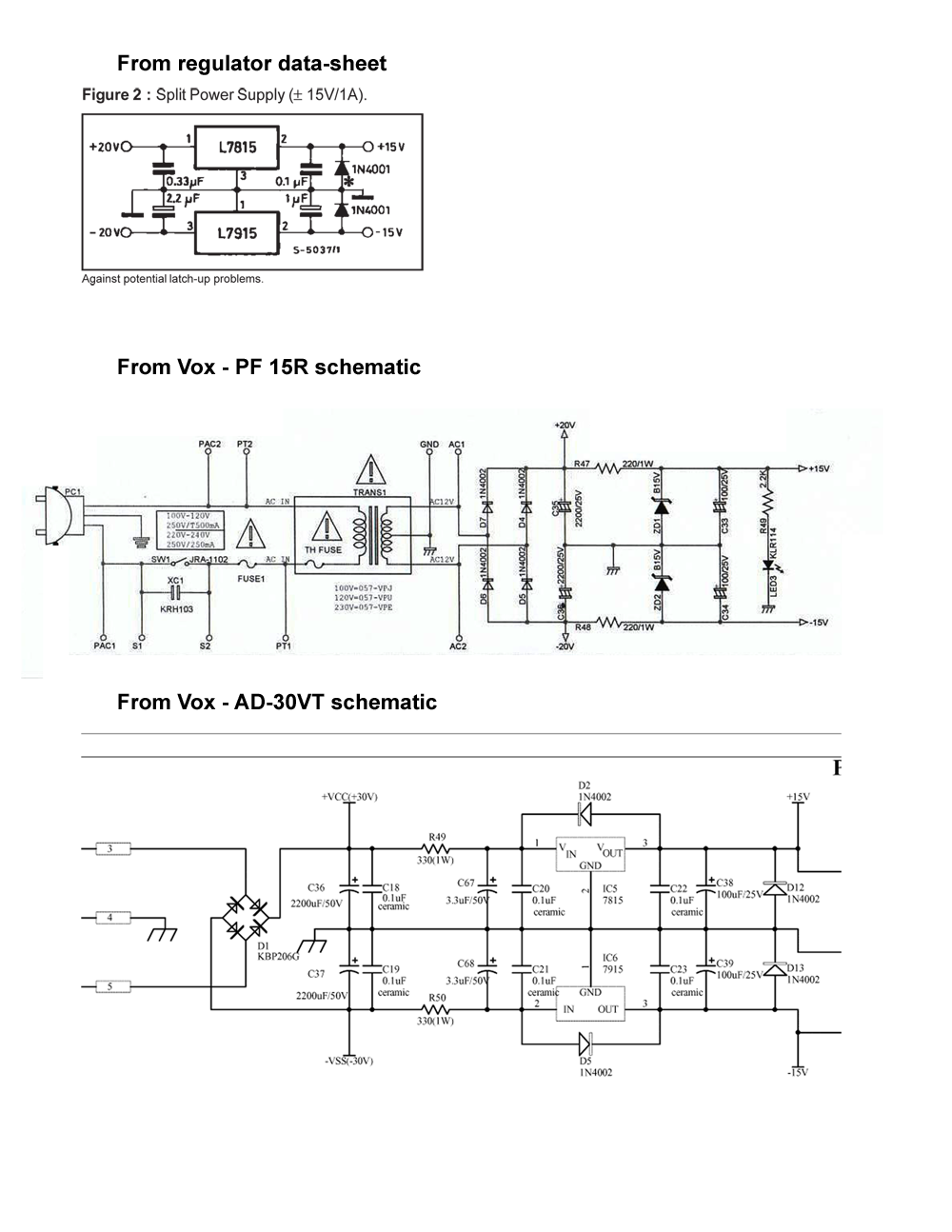
Next step in my quest to increase power in Vox PF. I purchased a Signal transformer 241-8-36 specs are :36VCT (18-0-18) - 2.8Amp - 100 VA. Rectified 18v should bring me to 25-26v . I'm currently looking at the voltage regulation down to 15V. Initial thoughts were to use 7815,7915 regulators. This is still an option but chassis space is limited and running leads to the "regulator board/heatsink" has me concerned, each of the 4 leads will need to be at least 5 inches long. i've compared some of the small Vox ss power supplies and was going to use a regulator set up based on the AD30VT Then noticed that the AC30VR and VR30 use 3W 15V diodes (1N5352BG) with 3W-10W resistors. My plan is to power an LM3886.

Researching further is see that Fender uses a similar setup on the Frontman 65R and 212R amps.
Is the combination of higher wattage diodes and resistors "safe"? It seems to be a fairly common practice.
Researching further is see that Fender uses a similar setup on the Frontman 65R and 212R amps.
Is the combination of higher wattage diodes and resistors "safe"? It seems to be a fairly common practice.
#4
Amplifier Discussion / TDA2040 Fail into Vox PF15R, LM3886?
October 20, 2012, 03:02:22 PM
In trying to add some clean headroom to the Pathfinder in addition to hopes of running a 4 ohm speaker cab I upgraded the 4 diode based rectifier to an 8A bridge (out of stock on 4A), increased the 2 main filter caps to 4700 50v ( upgraded additional caps to 50v as well knowing that a new tranny was probably to come), and used a TDA2040. Fail, clipping galore. So now I'm looking to upgrade the tranny. If I'm doing that why not use an LM3886 instead? I'll need to add a larger heatsink as well. I'm hoping the pcb and traces will support the extra voltage, only one way to find out I suppose.
I am unsure of what transformer to use. Searching this forum as well as others I've found many conflicting opinions. I'm looking at the Hammond 187E48, http://www.mouser.com/ProductDetail/Hammond-Manufacturing/187E48/?qs=sGAEpiMZZMvwUzoUXIIvyQPvPmwnNFGyvtncIbvtsVQ%3d. Would that work properly? Thanks
I am unsure of what transformer to use. Searching this forum as well as others I've found many conflicting opinions. I'm looking at the Hammond 187E48, http://www.mouser.com/ProductDetail/Hammond-Manufacturing/187E48/?qs=sGAEpiMZZMvwUzoUXIIvyQPvPmwnNFGyvtncIbvtsVQ%3d. Would that work properly? Thanks
#5
Amplifier Discussion / Replacing 4 x 1n4002 diodes with rectifier bridge
October 11, 2012, 08:45:34 PM
I'm upgrading the ic on a Pathfinder from a 2030 to a 2040, at the same time replacing the main filter caps from 2200 to 4700. From research I believe this will allow me to safely run the amp with a 4 ohm load. The rectifier diodes are 1N4002s and first thought was increase them to 1N4006s but I believe a single rectifier bridge would be better, the KBU403. One thing I haven't determined is the pin match up. Looks like the (+) at D7 anode and the (-) at D5 cathode, is that correct? If so what about the other 2 legs? Thanks
#6
Amplifier Discussion / Possible to control the Boost level on a Vox Pathfinder?
August 23, 2012, 12:42:34 PM
In this thread http://www.ssguitar.com/index.php?topic=2559.0 n9voc went into the way the boost functions on a Vox Pathfinder and how to disable it:
You are correct in that the "second stage" is always in the circuit. However, when the boost switch is NOT engaged, Q1 (the FET in the feedback path to the second amplifier stage) is turned "on" making the feedback resistance equal to approximately 22 kohms (value of R8) - effectively superceding the value of R6+R7. The gain of this stage (as all op amps) is determined by R(feedback)/R(input) - the input value in this case is approximately the value of the 22k resistor right before the capacitor attached to pin 6 of this IC.
All that being said, with the boost switch "off" the gain of this amplifier stage is approximately unity or "1". Turning the boost switch "on" shuts OFF Q1, and the gain then becomes (150k [R6] + 470k [R7])/22k [R5] or (to work the math) approximately a gain factor of 28. (HUGE difference!)
Indeed the LEDs work in the Overdrive drive function.
The Tremelo is the center portion of the circuit, which is coupled to the preamp by the optomodule (note between R19 and C18).
So, all that being said - and to keep all you like, losing ONLY what you don't the modifications become easier:
Remove Q1. Place a wire in the spots formally occupied by Q1 drain and source. Remove the optocoupler, run a connection between R19 and C18 (where two pins from the optocoupler used to be.
Now, you have the preamp without the boost, and without the tremelo. In circuit form, you have set the Trem setting to ZERO, and the boost switch to "OFF" permanently.
My question is how would you be able to control the amount of the boost with a pot? Thanks
Pages1