Menu

Show posts

This section allows you to view all posts made by this member. Note that you can only see posts made in areas you currently have access to.

Show posts Menu

Messages - R.G.

#46
Quote from: teemuk on August 28, 2009, 01:35:44 PM
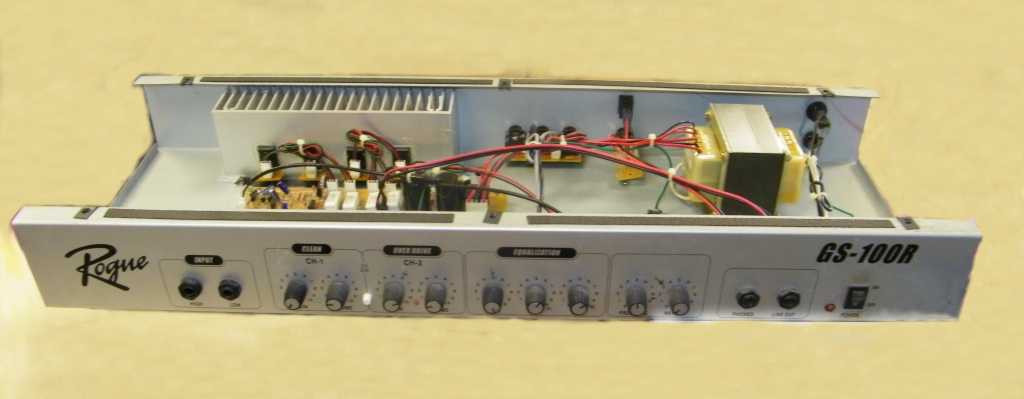
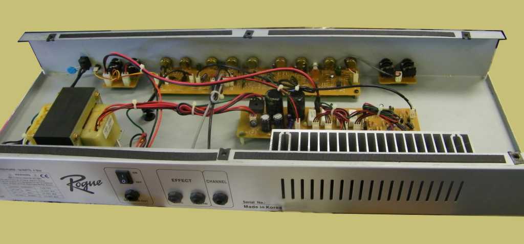
Am I looking at it correctly; are all of those power transistors contained on their own little boards? Wow, that's something I've never seen before.
Yep, you're seeing it correctly. Actually, that's one of the problems with this amp. Since I now own it, I did some checking on the reputation. They seem to inspire only two reactions - "good value for what I use it for" and "... cheap, nasty sounding junk".

I think both of those are correct. The entire amp is interconnected on those little white plastic connectors so the boards can be connected with stick-in cables for fast assembly. First of all, small connectors can't carry a lot of current. The output transistors have to put out on the order of 11A peaks, and that's going over *1* of the pins in a little square-pin connector. Get some dirt on it, let it heat up and get loose, and you have a power intermittent.  Then there's what vibration do to the connections. On top of that, every single control and jack is PCB mounted - in some cases, the PCBs are also "jack-mounted". The proximate cause of mine being $40 was an intermittent input jack - and it was obviously because someone bent on a plugged-in plug hard enough to crack the plastic jack and PCB. PCB mounted jacks, pots, and switches are a Very Bad Thing in guitar amps.

I just received a couple of pairs of Toshiba power transistors to replace the marginal TIP3055/2955 pairs, and I'm going to solder the wires to them, not PCB- and plastic-connector interconnect them.

I believe the all-PCB, all-the-time construction was a manufacturing saving. You could use a break apart PCB which contained ALL of the circuitry, including traces interconnecting the various little boards, then populate, wave-solder, and test the complete board. Once a board was known-good, the boards were broken apart, screwed into place, then connected with cables. Less handling, less labor, cheaper.

I'm *glad* they did it that way - it gave me a bargain.
#47
Yeah, it has a short spring unit in the bottom.

My personal interest in this one is that I have recently made PCBs for the preamp section of the JMI Vox Supreme and 7120 amplifiers. I intend to put one or both in this chassis. I may also graft in the limiter and perhaps even a transformer-driven power amp.
#48
Yeah, the Rogue is just what I happened into. However, it's a bit of a bluebird since it's got a lot of space and is uncluttered, as well as being made out of stock parts. It's easy to put in your own stuff. And you're unlikely to have any competition for buying them.  :)

I did take a couple of photos.
Front view:

Back view:


I think Dr. Frankenstein would have been proud of his assistant for digging up this one.  ;D
#49
Amplifier Discussion / Re: Safety Tips
August 28, 2009, 09:59:08 AM
Let me add to this:
- it is not possible to put in enough safety tips that you are safe from harm when messing with electricity; you are always putting yourself at risk when you play with hazardous voltages and currents
- read what the pros say; find yourself a book on electrical product safety, something about meeting IEC 600650 or UL600650.
- realize that by creating or modifying anything which uses AC line power, you are creating the possibility of a shock or fire hazard not only for yourself, but for anyone who ever comes in contact with what you've done, possibly years later.

If I'm sounding like a party pooper, forgive me. It's not a party if you electrocute yourself or someone else or start a fire. All of which have happened.

Some specifics, which, as I said, are not alone enough to keep you safe:
- In general, if you can buy a widget which comes pre-approved by a safety organization, you are paying a bit of money for someone else with training to have figured out what's less hazardous for you. A few bucks is far cheaper than a funeral  :)
- Use a three-wire AC cord, with safety ground. Don't think you can be clever or smart enough to successfully follow all the dance steps for safety with double insulation, the only recognized safety requirements for two-wire power.
- Use an IEC power inlet jack like this: http://www.mouser.com/catalog/specsheets/KC-301138.pdf which does several things for you: it lets you use modular cords; it eliminates you having to figure out how to strain relieve a power cord; it incorporates a fuse holder; it has been pre-tested by safety testing labs and is certified to be "not known to be hazardous" (which is NOT the same thing as known safe). This one sells in the USA for $2.09 at the time I wrote this.
- If you want, there are IEC inlets which have AC power switches AND fuseholders in them, eliminating another place for you to accidentally mess up your AC wiring.
- Once you get out of the power entry module, as Joe says, your first order of business is to get the third-wire safety ground bonded to the chassis. Which means, among other things, that you must have a metal chassis to bond to. One way to do this that has been accepted by safety labs before is the following: Drill a hole in the chassis; sandpaper a 1"/25mm diameter area around the hole down to clean, bright metal. Stick a screw of at least #8 or M4 through the hole from the outside and put a toothed/star washer over the screw. Place the ring terminal of your green safety wire (yep, you had to crimp on, not solder, a ring terminal to do this right) over the star washer, ensuring that the teeth of the washer touch the ring. Over that put a star washer, and over that a nut. Tighten the nut down snugly, making sure the star washer teeth bite into the chassis and the ring terminal. Anything less than this procedure can let the ground connection work loose with vibration and/or metal creep, and may set you up for shock hazards in the future. Loctite can't hurt, but the star washers are what holds.
- Use heat shrink on any exposed AC power terminals
- Either do proper crimps on Faston terminals and ring terminals or properly solder AC power wires. Solder may NOT be used for pressure connections, and do not tin copper wires which are put into compression terminals, like screw terminals. Why? Solder creeps under pressure. Tinned wires which are held by pressure in screw fittings can become loose over time and make a fire hazard.
- Test your input jack ground for continuity to the ground prong of the (unplugged!!!) AC line cord. If it's not continuous, you have a safety problem, because all accessible metal must be grounded.

This is just a smattering. Go learn and be safe.
#50
Quote from: ponchojuan on August 26, 2009, 09:05:40 AM
Damn this is a horrible thread.  So much misinformation and pundit opinion.  I encourage everyone to read an amplifier design book like G Randy Stones, or any of the other good design and theory books out there,  before proclaimating expertise.  Let's not create threads of misinformation.

Tee-hee... I do love a good Sorcerer's Apprentice post!

So, Poncho - how long have YOU been designing electronics? Or even reading electronics books? And, as JC85 says, can you point out what parts are misinformation?

It turns out that I *have* read Slone's (and it's SLONE, not Stone) book, and Doug Self's book, and quite a lot of the reference books and papers they quote, from present day right back into the 1950s and some a lot older than that. And I do have degrees in EE as well as decades of practice in designing and implementing (those are NOT the same thing!) audio devices, including guitar amps. Including both custom gear for some pros and commercial production products.

So, Poncho, enlighten us poor, benighted amp hackers - what parts are misinformation? More importantly, what is the correct information for the parts that are misinformation? As you might guess, there will be some documented followup on those... 8-)
#51
It's getting on 15 years now since I first noted on usenet, then later the web that the mechanical, not electronic, part of building effects is the hard part. This is even more true for whole guitar amps. Physically constructing an enclosure which will hold speakers, making and fitting a chassis into the enclosure, mounting a heat sink and power devices, and making a good (enough!) looking front panel are far more difficult than building a circuit board and getting it to run.

However, the process of Technological Cannibalism can speed things up a bit. Finding a commercially available product that is **physically** close to what you want to do and then modifying it to be exactly what you think you want is much, much easier. Think about it - even custom car builders don't, as a rule, start by machining up frames, engine blocks, wheels, etc. Instead, they take an existing car and "improve" it, even if their idea of improvement doesn't match yours.

Thanks for staying with me through the intro. We're getting down to the meat of the issue.

I ran into a happy accident that prompted this note. Some industrious searching may make you the happy recipient of something similar. In scanning the local craigslist, I noticed an ad for a "Rogue" guitar amp. I would not normally give a no-name amp a second look, but I did read the ad. The ad claimed a Rogue GS-100R amp, with 2-12" speakers and 100W output. I did a search on that and found that these were a house-brand made for Musician's Friend in 2001-2005. They still sell an upgraded version, the GS-120R. They're around $200 new.

But old and used? They're CHEAP! The craigslist ad had an asking price of $40, and said it worked, with some crackles. $40 might, maybe, possibly buy a single power transformer for a 100W amp. And I get for my money not only a power supply, but also heatsinking (which may need improving!), a chassis, enclosure, speakers which speak if not perfect, knobs, AC power wiring done? Such a deal!

In short, I picked it up and it's a beautiful candidate. The enclosure is as nicely done as I could do. The chassis is big, roomy, and easy to modify. The power amp is a discrete-transistor design on a single PCB with the power circuitry. The power transformer is big (always good for power thingies!). The heatsink is enormous, probably because they neutered it by placing it where it can't get airflow through the box, so they made it huge.

The physical arrangement is such that you could easily put in your own circuitry and have a working, usable and gig-able amplifier. How many of you have ever played a gig with an amp you've built? It's not that the circuits won't work, it's that you can't box it up well enough to survive transport.

In any case, if you can locate a Rogue GS-100R at a cheap price, it's worth your time. Even if it's completely non-functional. They were only $200 new. How expensive can they be 4-8 years old and unloved?

The one I got had a broken input jack. With a replacement jack, the amp was good as (it ever was) new. It's LOUD as you'd expect for a 100W, 2x12. The clean channel is good for effects users, since what you want with effects is to hear your effects, not the amplifier blender-izing them. The built-in distortion is pure, unadulterated crap, to be listened to as a bad example. But good distortions are a dime a dozen these days. Good enclosures, power supplies and power amps are not.

Try it. You may like it.
#52
Amplifier Discussion / Re: Grounding techniques
February 29, 2008, 09:15:45 PM
There is a progression from the premium approach to grounding being planar at far ultrasonic and RF toward send/receive pairs at low audio and DC. A ground plane approach is flatly wrong for high power at low frequencies. Matching send/receive planes is nice at low frequencies because of the low inductance and inherent capacitances to paired planes.

The problem with just a ground plane at audio is that you get returning signals and power (what I call "sewer ground") mixed locally with reference ground for amplifier circuits. One good example of how this is bad is using a chassis for a "ground plane" in some guitar amps. Another place you really, really need an isolated "ground" return wire is the power return from a speaker.

Yes, for high speed logic, RF and video, planar approaches are the place to start. It helps that the frequencies are so high that local decoupling can supply enough pulse energy to smooth things on the plane out. Leave out the local decoupling and the planes can't do it all.

One prototyping system I like a lot is called "dots". You use a punch and punch out 1x10E6 1/8" diameter "dots" from PCB stock. Then you use an un-etched PCB sheet with dots epoxied to it wherever you want a connection. Part leads go from dot to dot, or dip to the ground plane where you want ground. It's artistic, flexible, and fun.
#53
I can't tell you much about it other than the stuff that Gabe puts out as an explanation for why his solid state stuff sounds just like tubes is technical gibberish. It may or may not sound good. But whether it does or not is not because of the reasons promulgated for it.
#54
Amplifier Discussion / Re: LM1875 - need help
November 06, 2007, 06:53:53 PM
You know, Daniel, most of the people here are the same ones you asked over at DIYstompboxes.  :)
#55
Amplifier Discussion / Re: chipamp vs transistor
September 17, 2007, 08:04:33 PM
Shall we have another go at this?  :)

In my opinion,
(a) there is no "best" in terms of sound; (a1)all modern power amps are variations of the Linn architecture, whether discrete or integrated, including all the power amps I've ever seen in SS guitar amps with the sole exception of Class D stuff. The Linn architecture is great at hiding the individual inner sounds of the amp; and (a2) anything that the amp does as a "tone" can be done out side the amp if you try hard enough. (a3)Taking that further, people form uninformed opinions based on some experience and cling to them with a death grip, simply because that's what they've always thought. Changing your opinion is HARD. Which would you rather do - change your word processor or your spouse? (a4) As a result, ask ten people what is "best" on anything, you probably get ten answers and because there can be no disagreement about a matter of taste they are all ten right!
(b) using an amp with no protection is begging to get the amp destroyed when something untoward happens. See the long discussion on this in "schematics". A guitar amp that doesn't concern itself with protection is either (b1) short lived or (b2) overbuilt and has not ... yet... hit a situation outside the overbuild. And (b3) protection per se is not invasive if well designed. If correctly designed it is ... protective. A case which would activate the protection would damage the amp without the protection circuits. (I believe we got to there, yes LJ?)
(c) Outside the supercilious "protection equals bad tone" argument, and the "best tone" arguments, there are real, measurable decisions to be made in terms of difficulty to build, which presumably, is why you are here. For that, there is no question. Use chip amps. Building a 100+W discrete amp is an exercise in practical electronics that many professionals muff up. Where the wires connect to one another can make a non-specious, non-mystical, measurable difference in how the amp sounds. In a discrete amp, there are necessarily more critical elements that have to be hand wired, and hence are easier to muff up. If you're not already adept at building electronics, chances are good that you'll have trouble and settle for less than the best an amp can give if you go non-chip. Not because of voodoo or the Invasion of the Protection Circuits, but because there are a lot of manual construction things that have to be done right to get the best any SS amp is capable of. In a chip amp, at least a lot of those are tucked away inside the chip.

In my opinion - put a 50-60W chip amp in for each speaker, as most 100W's are at least dual 12's.   That will get you your 100W in an easier to build package, make finding parts (like transformers and capacitors) easier and at the same time give you some back up if your construction wasn't perfect or if the bass player spills a beverage into the back of the amp.  :)

And that's my opinion...
#56
Quotethe ears are enough.
Your ears may be better than mine. I can't get mine to turn out numbers for comparison.

QuoteI'll file away the advice tho. I do basic calcs ok, the old e=i2r, e=ir, p=ei, etc.

P = E*I and I = V/R, so

P = (E*E)/R

But for AC, P, I, and E have to be RMS, and we most easily measure peak. For a sine wave, you only need one more equation, Vrms = Vpk*0.7071, or its inverse Vpk = Vrms*1.414.

Those last additions let you run back and forth, figuring sine wave power. So if you can memorize only one more (say, Vpk = Vrms*1.414) you get a whole new level of usefulness. That's also how it works with AC power from the wall, so you can calculate power supply voltages from RMS too.

Stretch! Think of it as mental Yoga.
#57
Watts are easy to measure. You put a resistive load to replace the speakers. Then you feed it a sine wave and watch the sine waves on the output as you turn it up until they just barely start to distort on peaks. When that happens, you note the voltage on peaks and you're done except for a little light calculator workout.

The power of a sine wave into a resistor is fixed mathematically. The RMS value of a sine wave with a peak of Vpk volts is Vpk*0.707. The power which a sine wave voltage of Vrms produces in a resistor R is
P = Vrms*Vrms/R.

60W into 8 ohms is Vrms = SQRT(60W*8) = 21.9Vrms, which is the same as 31V peak for a sine wave.

So go run a sine wave into it, and watch the output sine wave on a scope. If you can get to 31V peak without clipping into a load of 8 ohms, it's putting out 60W.

The same goes for 4 ohm loads, only the numbers vary.
#58
Amplifier Discussion / Re: Fender Frontman 15G
August 16, 2007, 08:13:40 PM
Quote from: Blacklabel on August 12, 2007, 05:00:26 AM
hi, thanks for all you help everyone but now its just blowing fuses :'(..so ive given up on it :trouble..ill use the case and pots and speaker for another project...and i suggest every one bypasses the fender frontman series when buying an amp....too much trouble..but i thank every one who has helped me out....
You got some good advice early on that you haven't taken yet.

You can't debug fuse blowing problems very effectively if you only get 35 milliseconds of test time before the next one blows.
Quote
First: Before you turn the amp ON again build yourself a current limiter out of a light bulb that plugs between the amp and the main receptacle. It will prevent any further destruction.

http://repairfaq.ece.drexel.edu/sam/tvfaq.htm#tvtslbt
http://www.diyguitarist.com/PDF_Files/AmpCurrentLimiter.pdf
Go do it. There's a cleaned-up version of this at GEO (http://www.geofex.com) that is a little safer wiring as well.

But do it. That will let you quit tossing in fresh parts to wherever someone thinks you MIGHT have a problem.

There is a disciplined way to go about this.
1. Get the fuse blowing to stop so you can test voltages.
2. Test the power supply and get it running correctly, not blowing fuses
3. Remove the limiter and test individual pieces.

What you're doing in asking "Anybody know what it might be?" is asking to be told to replace a whole chain of expensive parts in hopes of eventually replacing the one or two failing ones by random luck.

Do the limiter, then get back here and we'll go to the next step. I've helped lots of people get running again with remote debugging. Maybe we can help you too.
#59
Amplifier Discussion / Re: Fender Frontman 15G
August 16, 2007, 08:12:08 PM
Quote from: XinTX on August 09, 2007, 01:34:12 PM
Quote from: R.G. on August 09, 2007, 12:27:19 AM
Well, there are several obvious design flaws I see in the schemo.
Such as? 
1. It perpetuates the Fender Mistake of using 15V zeners to power opamps. CR11-12 should be replaced with 7815/7915 regulators and R48-49 lowered to 150R 1W.
2. I can't find any local decoupling for U4
3. No local decoupling for opamps
4. board-mounted pots and jacks

Those are the ones that come to mind immediately.

#60
Schematics and Layouts / Re: 60W Power amplifier
August 14, 2007, 04:06:02 PM
And for my part in the heat, I apologize. I just can't stand to see things that are technically untrue bandied about as truth.