Menu

Show posts

This section allows you to view all posts made by this member. Note that you can only see posts made in areas you currently have access to.

Show posts Menu

Messages - Little Ricky

#1
Amplifier Discussion / Re: Speaker impedence question
November 26, 2012, 10:48:03 AM
Thanks phatt, I'll give the series wiring a shot as well. Without the ext cab it it might not have enough  output.  I'm getting asked to deliver too much from a 15w ss amp.

That being said I'm working on another Pathfinder and taking J M Fahey's idea of adding a separate power amp to the cabinet.  This is a friend I'm working with and I really want to make him happy. Which is tough because we started with the wrong amp.
#2
Amplifier Discussion / Re: Speaker impedence question
November 26, 2012, 10:39:39 AM
Thanks guys.  2 16ohm drivers it'll have to be. then the extension will bring it back down to 4 ohm when used.

The combo is one of my many Vox Pathfinder projects. This one with a TDA2040  so it can run the 4 ohm load. It's been running happily for 8-10 hours of gig time at 4ohm,even so  there is NO way I'd want to push that.

This amp has become like luggage, I can't get rid of it, it keeps coming home :). "Can I get an amp just like the one you put together for.....?",  Done. " Can it be louder?" Done. " Can it be cleaner?"
Can somebody please shoot me? :)


#3
Amplifier Discussion / Speaker impedence question
November 26, 2012, 09:20:54 AM
I'm looking to ad an extension speaker to a combo that has 2x8ohm speakers in parallel (4ohm). Looking at the illustration I take it that the top setup will yield a 6 ohm load and the bottom a 12 ohm load. Does this sound right or am I completely off the mark. Thanks
#4
No that wouldn't do it. What you're looking to do is interrupt the signal from going to ground. Sounds like you're trying to ground the  signal?

I would really just remove them. You should be able to do it without even removing the chassis (which is time consuming) .
#5
Sorry just getting back into things. As far as legs on the led's it really doesn't matter, they just connect to ground. Looking at the board I used the top 2 as they were accessible. I bridged the 2 together and connected that wire to one side of the switch. The other side of the switch gets soldered into one if the two holes in the board that the led legs were lifted from, you are just continuing the circuit.

If you want versatility add the "Raw" control
#6
Thanks. Amazing what you guys can explain clearly in 2 paragraphs that "get me" in the books.

I understand commercial amps, especially budget commercial amps are speced by the bean counters. Is there any reason other than saving a penny that Vox would for example use these "under recommended" values. Is there a sonic difference?

The recommended values for a 2030 are:

  • c5-100uf
  • c5-100uf

Yet Vox uses:

  • c26 (c5)-1uf (actually on board is a 10uf)
  • c23 (c5)-10uf

And for the resistor in the Zobel network they use what looks to be a 7ohm
#7
I had installed a tda2040 in place of a tda2030 in a Vox Pathfinder. It clipped horribly and I'm currently upgrading the transformer amd chip to an lm3886. But I'm still not suer why it was clipping. I thought there was not enough juice from the transformer. J M Fahey  mentioned it might be ocsillating, and I only heard the clipping.

I've been going over the spec sheets for the tda20XXs and the schematic for the Pathfinder. I noticed the the supply bypass caps on the PF are under recommended values for a 2030, which would make them way under spec for a 2040. Notes on the spec sheet warn that lower values may cause oscillation. JM was probably right all along.

My main question is why a manufacturer would choose such values for the bypass caps, I'm sure it was done for a reason.

#8
I've done the led mod on 4 PFs . The first I lifted one side on each led, insulated with hot glue and left it that way thinking it would be easier to put back to stock if I wanted. The second I lifted 1 leg each , tied the legs together and connected a mini-switch. The other 2 I just removed the leds.

The switched PF helped see exactly what the difference is.  Basically you lose the "cheap distortion pedal" sound and get more of a tubish breakup. It is a little noticeable at home volumes when played fairly clean. It's also a bit louder with the leds removed.

It seems the louder the amp and more gain run the bigger the volume hit with leds installed. At home I typically run the volume at 9, boost on and use the gain as a volume control. Late 60s Stones is about as dirty as I ever play.  Running the PF like that it gets very loud for home with the tone I like, never gets really nasty. Switching the leds back in the volume drop is noticeable and gets  "buzzy".

As a test I turned the gain up high with the leds switched, instant "blizzard of nails" flip the led switch to off and there was a huge volume increase and the sound cleaned up. I think this is why there are conflicting reports on the volume increase as attributed to the led removal, if you play with more gain you get a bigger volume increase with led removal.

Another mod I've done is add a "Raw control". I used a pot as in place of the set midrange resistor, turn it enough and the tonestack is lifted from the circuit. Increase in volume and added gain.
#9
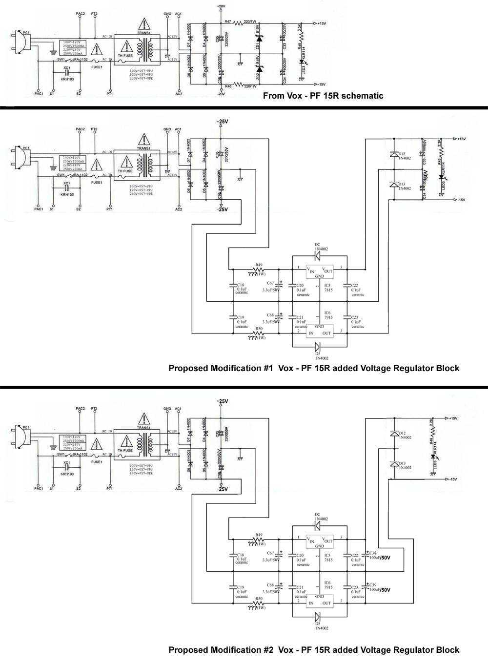
Right. I  am looking for different opinions . I understand the voltage Regulators  would be the correct way to do the job. As mentioned my other option was to replace the low spec resistor/diode circuit with higher value parts.  it seems like they are both viable solutions to the problem
#10
Thanks Roly.
#11
I would. You can do both mods right from the back of the pcb.
#12
Thanks. So as long as the regulators and all associated bits are together it doesn't matter how far away that separate board is?
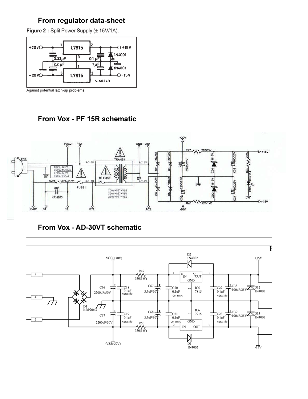
I noticed the PF and AD30VT switch the final capacitor diode pair. Does it matter which comes first?
#13
Next step in  my quest to increase power in Vox PF. I purchased a Signal transformer 241-8-36 specs are :36VCT (18-0-18) - 2.8Amp - 100 VA. Rectified 18v should bring me to 25-26v . I'm currently looking at the voltage regulation down to 15V. Initial thoughts were to use 7815,7915 regulators.  This is still an option but chassis space is limited and running leads to  the "regulator board/heatsink" has me concerned, each of the 4 leads will need to be at least 5 inches long. i've compared some of the small Vox ss power supplies and was going to use a regulator set up based on the AD30VT Then noticed that the AC30VR and VR30 use 3W 15V diodes (1N5352BG) with 3W-10W resistors. My plan is to power an LM3886.


Researching further is see that Fender uses a similar setup on the Frontman 65R and 212R amps.

Is the combination of higher wattage diodes and resistors "safe"? It seems to be a fairly common practice.

#14
I just tacked the wires to the trace side of the board, on the q side of the resistors.
#15
You may be right, I've ordered a transformer and associated bits. The worst that happens is it goes "POOF". Then I'll have to learn to repair it