Menu

Show posts

This section allows you to view all posts made by this member. Note that you can only see posts made in areas you currently have access to.

Show posts Menu

Messages - sa230e

#31
Well, it works. I was looking at the Big Muff Pi schematic and it used 10k for the series resistor so that's what I tried first and worked.


EDIT: However, when the bypass cap is removed the "collector following" returns and I had to up the value to 27k.

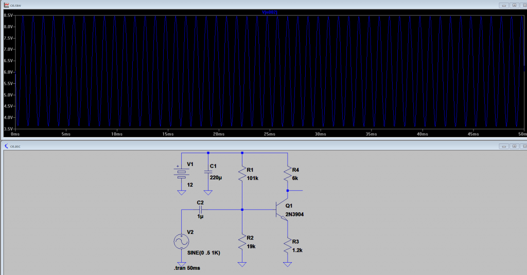
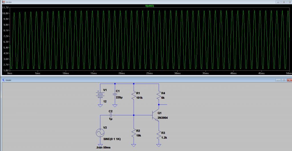
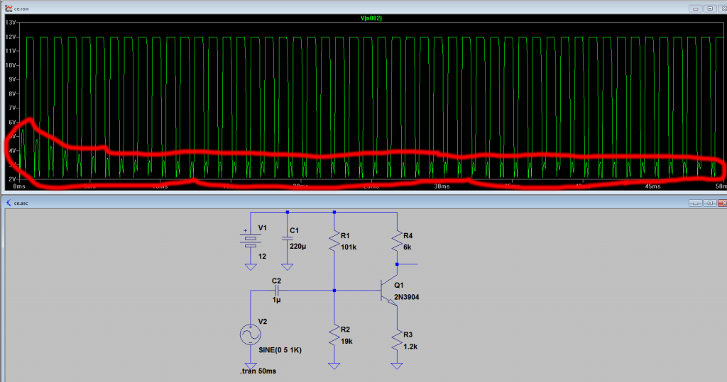
With no bypass cap and no series resistor the amplifier has a gain of 5. However when I add the 27k series resistor, the gain drops off quite substantially ( I measured it at 1.8 ). It seems like the higher the amplitude of your signal, the higher the value that resistor needs to be to keep the transistor from saturating BUT the higher the value of the resistor, the less voltage gain you get out. So they sort of work against each other.

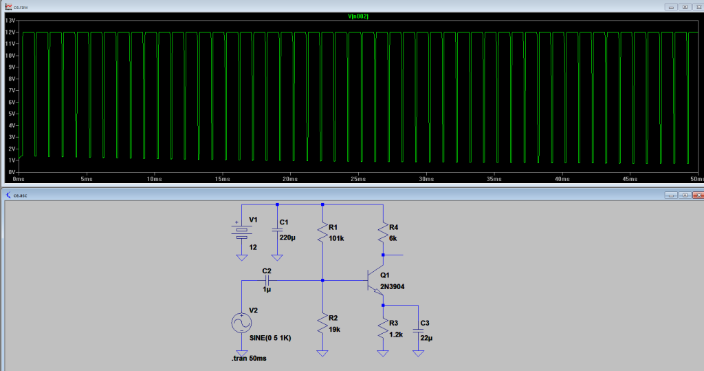
So it looks like if you want lots of gain without saturating the transistor, you NEED the bypass capacitor.

Interesting.
#32
Quote from: Roly on July 18, 2014, 01:11:13 PM
I'll just add that the effect that you have circled in red is called "collector following" - as said above, when the transistor is saturated fully on the Collector will then simply follow the Base drive, the whole acting as a simple resistive voltage divider across the supply, driven at the midpoint by the Base signal, i.e. the Base is connected to the Collector and follows it.

Thanks. Never heard the term before. You'd think it would be mentioned more often. Maybe with the prevalence of cheap op-amps designers don't even consider using BJTs for high gain amplification anymore?

Quote
Just a word of caution; sims like LTSpice are great these days, but they still are mathematical simulations, not the real thing and depend heavily on the quality of the device models used, particularly when it comes to modeling non-linear (overload) behaviour.  The ultimate "simulation" is to mock it up on the bench when every factor in the device "model" is taken care of because it's the real thing.

Yeah but it's the best I can do right now. I don't own a scope and can't really justify the cost so LTSPICE is a HUGE help for me. Generally, if something I design doesn't work in a simulator it doesn't work on the bench either so it saves a lot of time and effort.

Quote
Also; sims can only only show you what is "on circuit" and an amp that sims very nicely may have horrible hum if you are unwise enough to place the mains switch right next to the input socket (as I just witnessed on a build).  With some circuits such as Radio Frequency power amplifiers "off circuit" stray capacitances and inductances can become so significant they can make a nonsense of a simulation.  Guitar amps are pretty tolerant but there are still limits to the liberties you can take with "off circuit" physical layout and construction techniques.

Engineers have a saying - "throw it up against the universe (i.e. build it) and see what sticks".

I was planning on powering it with a battery or maybe a regulated wall wart so I don't think mains hum will be a huge issues. Point taken though. I have no interest at the moment of working with frequencies higher than audio frequency. I just want to build guitar gear.
#33
Quote from: J M Fahey on July 18, 2014, 08:07:41 AM
99.9% of people who write thousands of pages about tube vs transistor clipping HAVE NO CLUE.

Even BIG names, GURUS, etc.

When explaining things they DRAW nice little squarewaves and call them SS, then nice little rounded top and bottom sinewaves and call them Tube.

BOTH are wrong.  :trouble

Interesting. Actually that's another topic I was getting to: what the are differences (if any) in the way semiconductors clip. But I think that topic deserves it's own thread.

Quote
The only way to know is to SCOPE or its poor cousin: simulate.

Thanks God we have Loudthud here who belongs to the 0.01% who actually builds, scopes and posts.   :dbtu:

And now you who at least simulates, so you are in the top 0.1% ;)

I'm not going to lie, I don't simulate for the love of objectivity. I simulate because none of the things I build would work if I didn't. I'm just not anywhere near the level where I can design a circuit on paper and know how it will behave. If I disprove any "myths" to myself or anyone else, it's by accident. I'm probably labouring under as many naive and misguided assumptions as anybody.

Also, I'm kind of lazy. It's easier to throw something together in a simulator than on the bench. So I like knowing if something won't work before I go to the trouble of building it.

Quote
Yup, that´s how a single transistor stage clips when heavily overdriven.

What loudthud said is correct, once the transistor saturates, it becomes just a closed switch, collector gets practically shorted to emitter, so by definition both carry same voltage or signal, and whatever appears at the emitter will be at the collector.

So if driven by a low enough impedance generator, signal at the base will also appear, unchanged, at the emitter and the collector.

So while the transistor can handle it, the collector signal will be that at base or emitter (they track each other) inverted and amplified.
When saturated beyond that signal positive peaks will appear at the emitter/base/collector (when heavily saturated they become all the same) so also at the output, without phase inversion and unamplified.

Those are the little humps you see at the bottom.

Gotcha. That makes sense.

Quote
And yes, they sound annoying buzzy.  >:(

Try it yourself.

Add a series resistor between generator and base, vary its value between, say, 470 ohms and 22K and check its effect on the waveshape.

Thanks, I'll try it out.

Quote
One small redeeming factor that you didn't consider is that if you have a preamp , powered by, say, 12V as you show, and made out of cascaded simple stages as shown, most a stage will receive is what the earlier one can supply  ??? so probably 10Vpp (or even less) available will not make it act that funny.

Yeah that's what I was sort of trying to simulate. All I wanted was to overdrive the transistor. I didn't think it would make a difference if I did it with signal generator or another stage. It was just easier to set up the signal generator for 10v p-p than to build another stage.

Quote
One problem with simulation is that you can set it with "impossible"  parameters, in this case 12Vpp or more generator signal, zero impedance generators, etc.

Go one step ahead and add another stage after that one, drive it and post waveforms.

Things will start to get somewhat more reasonable.

Also remember that the first stage, which in theory could be driven with a powerful generator as supplied within the simulator, in practice will get a guitar signal, which by definition is weak (1Vpp tops, and that with heavy strumming) and quite high impedance.

Actually I didn't mention I was planning on using a JFET for the first stage to present a high input impedance to the guitar and avoid "tone-sucking".
#34
Quote from: Loudthud on July 17, 2014, 10:08:34 PM
In figure 3 the low impedance of the generator is feeding signal through the base-emitter junction (which is acting like a diode) and pulling up on the emitter resistor. This subtracts from the voltage available to the collector resistor. The transistor is saturated which means the collector to base junction is also forward biased so signal also feeds directly from base to collector without the usual phase inversion. C1 takes on a charge different for the quiescent no signal condition which makes the output wave shape change over the first few cycles. To minimize this effect you need a resistor in series with the signal on one side of the capacitor. Solid state circuits sometimes act badly when severly overdriven. The usual remedy (bandaide) is diode clipping to limit signal amplitude.

Thanks.  :tu: So how would you go about calculating the value of the series resistor? Does it matter which side of the capacitor it goes on? Does the resistor affect the gain of the stage?
#35
Quote from: Enzo on July 17, 2014, 05:22:54 PM
Your bias is not the voltage on the base, it is the voltage on the base with respect to the emitter.   At idle, what voltage is on the emitter?

Quiescent emitter voltage is 1.2v. The tutorial said it should be around 10-15% of Vcc.

Also, isn't the voltage of the base relative to the emitter constant (~0.7v) since it's a diode?

#36
Hey,

I'm a real electronics noob. I was really into it a couple years ago and I sort of put it on the back burner and now I've been slowly getting back into it - starting with the basics: simple amplifier circuits. I have some NPN BJTs and I want to use them to amplify a guitar signal and I've been reading tutorials and simulating some basic circuits in LTSpice and I have some questions.

Fig 1:

So I have this common emitter amplifier pictured (fig 1) and it works just as expected. The quiescent collector voltage is 6v (1/2 of my Vcc) it has a voltage gain of 5. I'm feeding it a sine wave with amplitude 1v p-p and I get a sine wave 5v p-p at the collector. So far so good.

Fig 2:

So I increase the input signal to 2v p-p (fig 2) and it starts to clip asymetrically. I thought transistors were supposed to clip symmetrically. The bottom half of the signal clips at around 2v but the top half is undistorted.

Fig 3:

When I increase the input signal amplitude a lot, to 10v p-p (fig 3) the output starts to get REALLY ugly. The top half of the signal clips at 12v just like I would expect but the bottom half of the signal gets these "humps". I've circled them in red. What is going on here? I can't imagine it would sound good. Also the "width" of the waveform seems to be distended, if that makes any sense.

Fig 4:

Now if I bypass the emitter resistor (fig 4), the "humps" go away (and the voltage gain shoots way up as expected) and the shape of the waveform changes even more. It looks a square wave with a very large duty cycle. I guess that would make sense if it was clipping very assymetrically but my bias point doesn't change. It stays centre biased regardless of the amplitude.

I was hoping to design a simple amplifier with a few cascaded BJT common emitter stages to get plenty of gain and distortion but I didn't expect the transistors to behave this way. I actually built a small amplifier with JFETS (1 stage common source unbypassed feeding into a JFET mu-amp) and I didn't get this effect. It clipped nicely and I was actually surprised at how good it sounded. Am I doing something wrong here? I admit I'm a newb and I've had a harder time wrapping my head around how a BJT works.

Thanks in advance for your help.

#37
The Newcomer's Forum / Distortion and filtering
May 01, 2012, 04:13:06 PM
I'm fairly new to electronics and I've been building and fooling around with basic circuits. Mostly common source amplifier circuits using JFETs to create distortion but the sound isn't all that pleasant. Kind of like the song Revolution by The Beatles. My best guess as to why is that I didn't really design the circuit to filter out any frequencies pre-distortion so what I'm hearing is ugly harmonics from the lower notes but that's just a guess. I don't have a scope to test it.

So my question is: How do you get a pleasing tone out of a clipping gain stage. I'm aware that's pretty subjective but generally speaking.

And also, how do the commercial amp manufacturers usually do it? I've looked at schematics but my knowledge of filters so far is still pretty basic. Most solid state amps seem to use active filters with complex networks of components in the feedback loop and I can't really wrap my head around what they would do to the signal let alone work out the cutoff frequencies. I realize that different amps have different tones and all but electronically they still use variations of the same "building blocks".

Any help would be most appreciated!  :tu:
#38
The Newcomer's Forum / Re: DIY guitar amp ringing
April 19, 2012, 11:44:05 AM
D'oh!

So it turns out I had the input jack wired up backwards. Oops! I simply reversed the wires and now it's nice and quiet - even without shielding. With a problem this frustrating I knew the cause had to be absurdly simple!

Thanks again for you help, though. I'm looking forward to participating more in the future with this great community!
#39
The Newcomer's Forum / Re: DIY guitar amp ringing
April 12, 2012, 06:49:25 PM
Tested it out with the container grounded this time and it made a HUGE improvement! Thank you so much!
#40
The Newcomer's Forum / Re: DIY guitar amp ringing
April 07, 2012, 12:27:20 PM
Thanks for the reply! I didn't ground the container so I'll have to try that next.

I did plug the guitar straight into the LM386 and had no problems. This project actually started off as a Ruby (http://www.runoffgroove.com/ruby.html) and sort of evolved from there. The JFETs are not there for lack of gain but for the tone. I didn't care for the sound of the LM386 by itself when driven into distortion. The idea is for the distortion to come solely from the preamp. I designed it specifically so the LM386 would not clip even at full gain.
#41
The Newcomer's Forum / DIY guitar amp ringing
April 06, 2012, 05:33:28 PM
Hey everyone. I'm still pretty new to electronics but I think I'm starting to get it. I designed and
built myself a little 9v battery powered practice amp as a first project and I'm having some trouble
with oscillation, I guess. I'm hoping someone here can help me out. It sounds pretty good a low to medium gain but as I turn it up more it develops this fairly high pitched (still easily in the audible range though) noise which sounds kind of like a ring modulator effect which just kills the tone.

I don't have a scope so I can't tell what the frequency is or exactly where it orginates. It doesn't happen in LTSpice but real life is often different from a simulator as per Murphy's law of :p . I think it comes from the second gain stage as turning the tone pot to the bass side reduces it significantly. Actuall just touching the tone or gain pots changes the frequency of the ring. If I touch the input jack or even the surface (not the traces) of the PCB the ring stops but the gain is also much reduced which I've never seen happen before.

I built it on a fairly generic piece of prototype PCB and I'm just bench testing it right now. I did try putting a metal container over it to shield it but it didn't change the sound. I've attached a schematic. Hopefully someone can provide some insight.

Any help is much appreciated!