Menu

Show posts

This section allows you to view all posts made by this member. Note that you can only see posts made in areas you currently have access to.

Show posts Menu

Messages - pinkjimiphoton

#16
yeah, you need a 14v-0-14v ac power supply, or 28vac center tapped. so yep, close enough.

i'm putting 6600uf caps in mine, they seem to run better with them. 2200 is ok, but quite a bit of ripple if ya run these hard. i tend to dime stuff, ....well.... i generally run the tone stack around 6, and the volume and gain dimed, anyways ;)

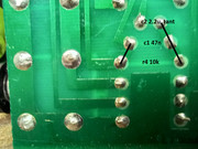
however i marked them big caps is how they are on the board, but there's parts that just are omitted here and there.. not even mentioned on the board. ;)

rob says i got that gain connection wrong, so i gotta check again WITH my beeper... but i think he's confusing the way the connection goes, cuz what you have now seems to match the drawing i had started and the board.

just to be sure, tho, i'm gonna beep it after dinner.
the jacks are like, identical to these:

https://www.taydaelectronics.com/hardware/6-35mm-1-4-plugs-jacks/6-35mm-1-4-stereo-insulated-unswitched-socket-jack.html
#17
Quote from: joecool85 on March 21, 2022, 02:25:20 PM
Quote from: pinkjimiphoton on March 21, 2022, 01:32:06 PM
that's beautiful!
personally, i don't like pots or jacks mounted via flying leads, and do like the full size board,
if just aesthetically.

but i'm stoked either way for your kindness and awesome work. thanks man!!!

I'm fine with (and often prefer) on-board pots, but jacks should never be attached via PCB.  WAY too high failure rate.

yikes. ;)
to each their own.

i'm a stompbox guy, to me, i don't like ANYTHING on flying leads with a high gain circuit personally.
and in repair, i've done more repairs on stuff with leads than mounted to the board.

if it were tubes, where they're being subjected to mechanical stress and heat, i'd agree with ya, but imho board mounted is just as easy to fix and tends to mess up a lot less.

but whatever works for ya is good by me ;)

#18
hey tassieviking, i think i found one other mistake...  i guess i was unclear in my description, and i just noticed it.

pin 1 of the gain pot connects to node of 10k and 47n on the 2.2uf tantalum side. so it's still off by that one connection. the 10k r4 and 47n c1 are in parallel. ONLY one side of them connects to pin 3 of the jelly bean.
the gain pot pin 1 connects to the other node, where the "input" of the rc network connects to the 2.2uf tant.

i did a q&d paint fix on it, this is how it needs to be:
#19
that's beautiful!
personally, i don't like pots or jacks mounted via flying leads, and do like the full size board,
if just aesthetically.

but i'm stoked either way for your kindness and awesome work. thanks man!!!
#20
this is awesome!

so stoked.... thanks so much, bro!
#21
hey Tassieviking,

here's the deal. your schematic, the last one, has only one mistake.

r4 10k and c1 47n are in parallel. one node connects to negative side c2/gain pin 1, the other to pin 3 of the 1458.

other than that, matches the circuitboard i have on my bench as far as i can tell completely, and am absolutely sure the preamp is right other than that one spot.

its hard to see. there's a couple traces that may not look connected cuz of the way the board was laid out, and cuzza that sticker that i hadn't removed from an inspector.

here's a pic, i drew lines to show the connections, and filled in the blanks with the part #'s and values


now... for measurements. board is 12.75" long by 4" wide. it sits on a 1 inch spacer centered at the back edge of the pcb.

from edge of board, j 1 center, between the mounting pins, is 11/16ths
j1 center is exactly 2".

pots are located at 3", 4.5", 6", 7.5", 9", 10.5" all 24mm

j3 is 11 14/16" from left edge of board.

28v center tapped transformer, 1 amp, like the hammond 166j28. it will fit the mounting holes in the original units.
#22
that's nice work, bro!
i dunno what rob is seeing, so let me take a peek when i go downstairs.
i don't usually mess with amps much, more of a fuzzbox guy.... had to get a small production run finished yesterday,
will try and get to measurements etc this afternoon.
just woke up, crack of 1 pm. musicians.  :dbtu:

the darlingtons you're using are hip, and probably a lot easier to find than the originals!

i will try and answer all specifics this afternoon. thank YOU for your hard work on this!

the reverb 12 is one of my favs. i just finished restoring one recently, but modded slightly... using a 10" 8r celestion gives a bit more balls to it, and i had hacked in an fx loop and a touch more volume to it by adding in a simple guitarpcb.com board called a paramix.

https://www.youtube.com/watch?v=PM4GKTYwGwg

https://www.youtube.com/watch?v=_u83mHMtrco

more soon. beware of random f-bombs etc in my videos if easily offended. they're rarely SFW, and usually not particularly good ;)


#23
hey now,
i posted this on another thread on the diystompboxes forum, my bro rob strand looked it over, and had the following to say:

Cool.  Thanks jimi and tassieviking.

I have *not* checked the trace/schem, however, the input stage didn't look 100% correct.

The no input cap is correct but the arrangement at the output of the first stage of IC1 looked wrong.
I posted the correction below.   The fix actually follows the other 5010 schem fairly closely, the only
difference is the other 5010 schem has an extra 100R on the output of IC1.


Bug on schematic Rev 1, 2022-03-19

(IC1 pin 7 goes to C4 (100p) and R6 (22k) as shown)

But then from IC7 pin 7 it should go,

IC7 pin 7 to C2+
C2- to paralleled C1 (47n) & R4 (10k)
other side of paralleled C1 (47n) & R4 (10k)
   to VR1.1 (ccw)
   and to IC1 pin 3

https://www.diystompboxes.com/smfforum/index.php?topic=35555.msg1243399#msg1243399

i have not had a chance yet to confirm anything myself. hopefully maybe tonite or tomorrow if i can get some time.

again, thanks! this nut's almost cracked.

i will get measurements too asap, promise.
#24
holy cow, tass!
that was quick!

looking at without the pcb in hand, it looks to be correct, but i will check it when i hit my workshop in a little bit.
i can definitely give you measurements.

i have another one of this particular amp, complete, do you want measurements for the chassis as well? thinking that may help not only with the spacing for the parts to layout, but also maybe you can make a proper front panel drill guide for the project as well?

i need to do this anyways, as i'm gonna mount this spare board in a hammond chassis i just picked up.

thank you for this! in your debt, along with all the rest of us messing with this in the past and future ;)
#25
Quote from: Tassieviking on March 18, 2022, 11:42:41 AM
I might give you a hand with this one, its late down here now so it will have to be another day.
well,  later today maybe as it's 2.30am here now.
I did find another photo of the track side of a 78-2 PCB so I mirrored it and marked out the components quickly.
On the picture the inputs are on the left.

you are god like!
i've been stalled. i'm really not very good at tracing stuff out at all.
i got it working again,  bought an aluminum hammond chassis to mount it in since it's just the pcb.
just need a chance to reassemble it all.

but for all intents, other than part numbers, mostly its the same as the other schematic other than a few part values.

thank you so much tassieviking! epic and helpful!!
#26
here's the BOM from the board i have,
hope it helps someone. still working on trying to draw up the schematic, wonky eyes suck!

5010 early version BOM
board jm78-2

vr1 gain b22k
vr2 volume al00k
vr3 treble b220k
vr4 mids b22k
vr5 bass a1m
vr6 pres b22k

ic 1 mc1458e

q1 bc184
q2 bc182
q3 bc182
q4 bc212
q5 bc184

q6 mj3001 darlington
q7 mj2501 darlington

zd1 9.1v <4739>
u
db1 br62

r= red box cap
t= tantalum
e= electro
c= ceramic

c1 47n@250 r
c2 2.2u@35 t
c3 2.2u@35 t
c4 2.2n c
c5 100n c
c6 2.2u@35 t
c7 2.2n c
c8 220n@100 r
c9 4.7n c
c10 220p c
c11 47n@250 r
c12 47n@250 r
c13 22n@400 r
c14 2.2u@35 t
c15 100u@25 e
c16 100u@25 e
c17 220n@100 r
c18 22u@25 e, axial
c19 2.2n c
c20 220p c
c21 100u@25 e, axial
c22 non existant
c23 2200u@25 e, radial
c24 2200u@25 e, radial

all resistors 5% cc  1/4 watt unless specified

r1 1m
r2 68k
r3 68k
r4 10k
r5 100r
r6 22k
r7 10k
r8 470r
r9 non existant
r10 22k
r11 68k
r12 10k
r13 33k
r14 4.7k
r15 2.7k
r16 2.7k
r17 10r
r18 6r 1 watt
r19 270r 3 watt
r20 470r
r21 10k
r22 3.9k
r23 4.7k
r24 680r
r25 10r
r26 2.2k
r27 1.5k
r28 1.5k
r29 1.5k
r30 10r
r31 39r
#27
Quote from: Spm5010MLC on March 05, 2022, 03:56:07 AM

I'm going to trace the complete board in the near future and will post for anyone who's interested.

Seems I do not have access to the attachments function so I can't post the images... hmmm.

Thanks!

hey bro, if ya click attachments and other options, it should give ya the option to upload pics... if not, shoot me a pm and i'll upload them for you.
#28
more pics   xP xP xP :o
#29
ok, here's some pics of the board i have. i'm trying to draw up a schematic, gotta take a bunch of notes and stuff and connect the dots, but so far it looks really close to the other schematic other than some part values and how they're named.
the input are two 68k in parallel with a 1m to ground. i've gotta draw the rest. later, i'll try to upload a BOM with the values as shown on the boards for all the parts.
lotta stuff to do. and i suck at this.
but pics:
#30
i saw that, thanks.... different from mine! ;)
mine has two inputs, horizontal, with a 1m resistor to ground and two 68k resistors like a fender. all but the smallest caps are red box caps, and the layout doesn't quite match. very similar, but not quite. i'll try and get some pics to post later.