So for a while now, I've been kicking around the idea of designing my own tremolo pedal.
Yes I know, good designs and schematics already exist on the net and I know that function generator ICs are pretty inexpensive and plentiful but I like to do things the hard way because I like the satisfaction of building stuff that's completely my own and, I guess, because I'm a sucker for punishment. So humour me on this one.
So the idea is to have 3 different waveforms to choose from: square, triangle and sine (and possibly sawtooth). There are probably more than one ways to do that but the plan is illustrated by this block diagram:
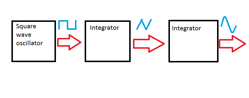
It starts with a square wave oscillator (probably a relaxation oscillator or possibly a 555) feeding into an integrator which should yield a triangle wave, feeding into another integrator which should give a sine wave (right?). Sounds pretty simple, except how do you design the integrators? More precisely, how do you choose the values for R1, C1 and R2? All the tutorials I came across need a university level math comprehension to understand - and I took (and passed) integral calculus in university! That was a couple years ago, though so it's all clear as mud now.
The only useful (to me) tidbit I could find was this:
There were some example circuits out there (didn't save the links unfortunately) for quick-and-dirty signal generators based on the same idea but they all work at high frequency. What if you want to integrate a very low frequency tremolo wave? Say 1 - 15 Hz? Do the values of R and C become so large as to be impractical?
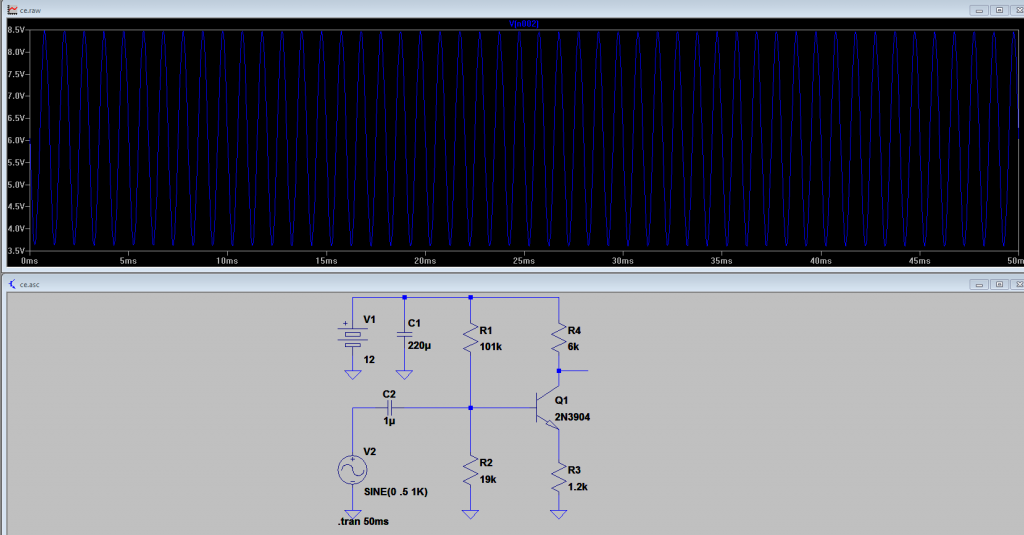
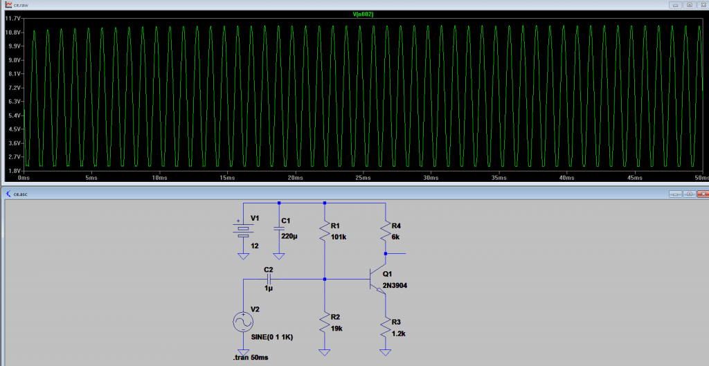
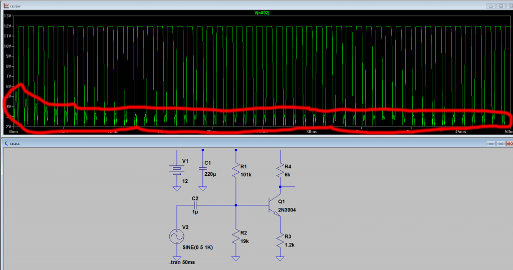
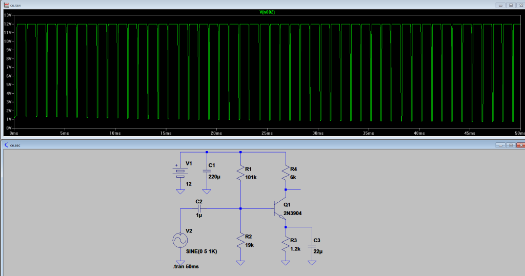
Playing around with LTSPICE, I couldn't get a triangle wave out of a square wave even with stupid large values of R and C.
Any ideas or am I just barking up the wrong tree with this one?
Yes I know, good designs and schematics already exist on the net and I know that function generator ICs are pretty inexpensive and plentiful but I like to do things the hard way because I like the satisfaction of building stuff that's completely my own and, I guess, because I'm a sucker for punishment. So humour me on this one.
So the idea is to have 3 different waveforms to choose from: square, triangle and sine (and possibly sawtooth). There are probably more than one ways to do that but the plan is illustrated by this block diagram:
It starts with a square wave oscillator (probably a relaxation oscillator or possibly a 555) feeding into an integrator which should yield a triangle wave, feeding into another integrator which should give a sine wave (right?). Sounds pretty simple, except how do you design the integrators? More precisely, how do you choose the values for R1, C1 and R2? All the tutorials I came across need a university level math comprehension to understand - and I took (and passed) integral calculus in university! That was a couple years ago, though so it's all clear as mud now.
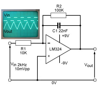
The only useful (to me) tidbit I could find was this:
QuoteTo produce a linear ramp on the output triangular waveform, the CR time constant of the integrator circuit should be similar to, or longer than half the periodic time of the input wave. In the case illustrated in Fig. 6.6.9, a time constant R1 x C1 (10exp3 x 22exp-9) = 220µs converts a 1kHz square wave with a periodic time of 1/2exp3Hz = 500µs/2 = 250µs into a reasonably linear triangular wave.
http://www.learnabout-electronics.org/Amplifiers/amplifiers66.php
There were some example circuits out there (didn't save the links unfortunately) for quick-and-dirty signal generators based on the same idea but they all work at high frequency. What if you want to integrate a very low frequency tremolo wave? Say 1 - 15 Hz? Do the values of R and C become so large as to be impractical?
Playing around with LTSPICE, I couldn't get a triangle wave out of a square wave even with stupid large values of R and C.
Any ideas or am I just barking up the wrong tree with this one?