Menu

Show posts

This section allows you to view all posts made by this member. Note that you can only see posts made in areas you currently have access to.

Show posts Menu

Messages - LJ King

#16
Schematics and Layouts / Re: Baldwin Professional
October 19, 2007, 01:01:00 PM

Channel 1 is the second or lower preamp, the one with Supersound. Channel 2 is the first or upper preamp.

The decoupling resistors feeding all stages of the preamp from the +22V supply should be 3.3K, not 33K. 33K is correct for the tremolo oscillator.

The 33 microfarad cap feeding the channel 2 volume control should be .33 microfarad, same value as the post volume 330nf cap.

A production change to the 50 microfarad decoupling cap in the input stage of channel 1 was made in 1966, an increase to 100 microfarads to "reduce low frequency oscillation at certain settings of the controls".

Also as a production change at the same time, the 1.5K emitter resistors in the second transistors of the input stages of both channels was increased to 2.7K to "reduce the overall gain of the amplifier to value consistent with general requirements" (don't you just love engineer coverup talk?  :lmao:).

Along with this "decrease the gain" change, the 47 ohm resistor in the feedback/tone control circuit of channel 2 was changed to 100 ohm.

The Reverb section. The 27K bias resistor for the input stage should be 2.7K. The reverb control is a 50K pot and is wired backwards from this diagram - the pot's wiper connects to the output/mixer gain stage through an 18K resistor before the 1 microfarad cap. (Think about what would happen if the footswitch were used with full reverb - very muddy sound).

The dry signal from the input stage emitter connects to the output/mixer stage through series connected 120K resistor and a .082 microfarad isolation cap to avoid messing up bias - not a direct connection. The output cap of the mixer stage to the power amp is a 5 microfarad value, not a 1.

The output stage driver - the 33K decoupling cap feeding the voltage amp stage is 3.3K The Custom has triple totem pole output stacks, not dual. And the speaker impedance load is 2 ohms. The .47 ohm emitter resistors are fuse wire, not actual resistors.

Supersound. Just some minor things. The two chokes are .8h not 8h.

The lower choke (as it is drawn) is not connected to the right side of the other choke - it connects directly to the junction of the .68 cap and 27K resistor... similar to the 10K in the Mid II portion - not through the switch connections. With it switched as shown, there would be no bass portion feeding through when the Mixture switch is activated (Mix is a bass/treble boost).

Unfortunately, Baldwin didn't specify transistor information. All NPNs are the same with the exception of the reverb input/driver. All PNPs are the same. The only info on the schematics is that the types need to be selected in accordance with an internal procedure reference number that varies depending on their NPNorPNP-ness (S429-1 and S438-1), with yet another for the reverb driver (S429-2). I haven't seen any of these internal procedures.

The outputs (at least for the Custom) are designated on the schematic as "TRPV", with the V being a roman numeral. They are Germanium devices.

Also worthy of some note - of all these amps I've seen, maybe 12 or so - all are handwired point to point using perfboard for support.
#17
The Newcomer's Forum / Re: I'm new here...
October 14, 2007, 01:16:07 PM
Don't know if it's the case here, but sometimes a request for more gain is a request for more or different sounding distortion.

#18
Amplifier Discussion / Re: Troubleshooting
October 11, 2007, 11:11:16 AM
I don't have a Mark III schem, but if it's similar to a Musician 400...

I only see one 4.7 ohm resistor - part of the preamp voltage regulator, which it's in series with the regulator output. The regulator is powered directly from the positive rail that goes to the power amp.

So this is the thought:

If the resistor is getting burnt it is drawing too much current. A primary cause of that may be a short after the resistor, and the most likely suspect to short is a 50 micro/50 volt electrolytic between the resistor and ground.

If the electrolytic shorts, the resistor would draw too much current and an excessive current draw would load down the positive rail. This could cause the hum since the power rails to the power amp would now be unbalanced.

Look for an electrolytic cap in the area around the resistor - there should be two of the same value.

Since the amp works for awhile before developing the symptom, it sounds thermal related - and I have seen electrolytics develop an internal short when they become heated sufficiently and appear to be functioning correctly after they cool down.
#19

I highly doubt that swapping one chipamp for another is going to give you more power. Chances are pretty good that the output will be limited by the current capability of the power supply.

More volume can be achieved much easier and probably cheaper by using more efficient speakers - I'm assuming you still have the stock Fenders?
#20
Quote from: legeorged on October 03, 2007, 01:55:47 PM
im new to this.  i have a sunn concert lead guitar head.  im looking for a cab for it.  (what ohms, how many, wattage, etc)  any suggestions?  looking for something loud, sturdy and affordable.  not too concerned with tone, mainly something i can kinda beat up on tour.


There are two versions of the Concert Lead. The early 2 channel model is rated at 150 watts at 4 ohms minimum load. The later single channel version is rated 200 watts at 2 ohm minimum load.
#21
Amplifier Discussion / Re: chipamp vs transistor
September 17, 2007, 07:31:32 PM

Just my opinion - -

The best professional equipment for guitar will be discrete. For bedroom practice, it really doesn't matter.

At 100 watts or so up to 150 watts, I'd rather have 4 discrete devices - 2N3055s, 2N3773s or the like, without protection circuitry to destroy the sound to protect me from obtainingthe tone I want, that can be replaced if necessary. Above 150 watts I'd rather have the same discrete devices but more of them, six or eight.

A chip amp doesn't do it for me.

A guitar amp doesn't concern itself with specs or invasive protection circuitry.

I've never used a Crate Block. Isn't it a digital amp - class D or the like?

The old Peavey stuff like the Standards and Musician 400 series are great sounding amps. I just got into them recently.

(yeah Teemuk I know the Peaveys have "protection stuff" but it doesn't interfere with the sound - just like the old Kustom K200Bs)

#22
Quote from: teemuk on September 12, 2007, 06:01:07 PM
About capacitor C3: This is highly subjective issue but I would rather try values closer to 10 - 47 pF. In fact, I might even omit the capacitor completely assuming the circuit stays stable without it. Anyway, if audible low-pass filtering is sought after then ignore my comments.

Wouldn't the -3db frequency provided by the value of C3 be determined by the series value of the 50K gain pot and R4?  :-\

I calculate a 100pf cap and 60Kohms to be at 26.5KHz. Your ears (and speakers) must be much better than mine to consider that as audible.  ;D  ;D

It is good to hear someone talk about pickup impedance rather than "DC resistance".  :tu:
#23
Schematics and Layouts / Re: Little Rebel
September 09, 2007, 08:15:19 PM
Quote from: joecool85 on September 09, 2007, 04:00:43 PM
Quote from: obelix on September 09, 2007, 10:16:56 AM
hey what happened to the pictures? :)

I'm not sure if I know what you mean, they seem to all be there.

Where is there? I don't see any pictures either.
#24
Quote from: teemuk on August 31, 2007, 06:17:43 AM
Isn't that the one with "blend" distortion feature on the effects channel? "Master Gain" control is the same as master volume.

The picture is one he got from ebay. He says his doesn't have the master section. But without an exact picture, we're still guessing.

I don't know if the Standard followed the Musician, but if it did I'd assume Luca's amp is an "A" series.

The Musician had both Distortion and Fuzz in the "A" series version which was early/mid 70's, also without a master section. Reverb was available in the effects channel only.

Then in the mid 70s, the "B" series version added the master section with reverb on both channels, "automix" channel switching capability, and gave the Fuzz a "Blend" control, and retained the separate Distortion effect.

EDIT: Aha!! Here is another stolen eBay pic of what the amp probably looks like:

#25

It's been a while, but a friend had one of those. I swear I remember the speakers being 16 ohm units. He sold it several years back, but I called him and he remembers them being 16 ohms as well - connected in parallel for 8 ohms total per side.

The ohms rating is the only reason I can think of why a particular 10" speaker may not be appropriate.
#26

Since I have this Dirt Road Special apart, I thought someone might like to see how it's put together. I have verified the second schematic posted in this thread and corrected a few capacitor values. If the input caps are showing something other than a value of "1", refresh your browser.


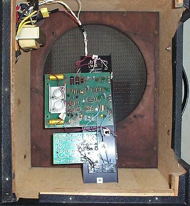
This is the insides. The speaker has been removed to provide some extra room to work with. The case and back panel are 1/2 inch particle board with the sides finger jointed in the corners. The front baffle is plywood. The wood strips used for mounting the back panel are stapled to the sides of the back. Similar strips are used to build up the front edge to hold the grille cloth and for the baffle to screw into. I'm sure that the small size helps, but it is a very sturdy case.

The power supply is in the upper left of the picture - transformer, open style fuse holder, bridge rectifier, electrolytic cap, and a .1μF (wired across the transformer secondary leads prior to the rectifier) are all wired together point to point with no brackets or spare lugs. The fuse holder is secured to the side of the cab, the transformer and electrolytic secured to the bottom with nuts and bolts through the cab. Everything else is "loose" with a few wires bundled with a plastic tie.

The "rats nest" of wires tie the power supply to the circuit boards. Three wires are separate grounds all coming off the main amplifier board. One wire supplies the B+, and there are two for the primary AC - one is routed to the power on/off switch and the other side of the switch comes back down to the fuse holder. There is no "chassis grounding" cap on the primary AC side, just the 1 amp fuse and switch.

All of these wires are single strand and a really thin gauge. They will break with the slightest nick, and several disconnected themselves as I was replacing the IC with a socket. I will be replacing all of them, and routing the AC lines separate from the others.

Of the two circuit boards, the smaller one at the bottom is the Small Stone phaser effect. The switches below mounted to the control panel are the on/off and Color for the phaser.

The preamp and power amp are combined onto the larger board. The single 4558 chip is for the preamp. The six TO-94 transistors and the two TO-3s make up the power amp. The two larger electrolytics are C20 and C21.

Both boards are secured to the control plate with the board mounted pots. There are also holes in the boards (left side in the picture) where screws go through the case, through a round, roughly 1 inch long plastic spacer, through the board and a nut secures the screw at the bottom of the board.


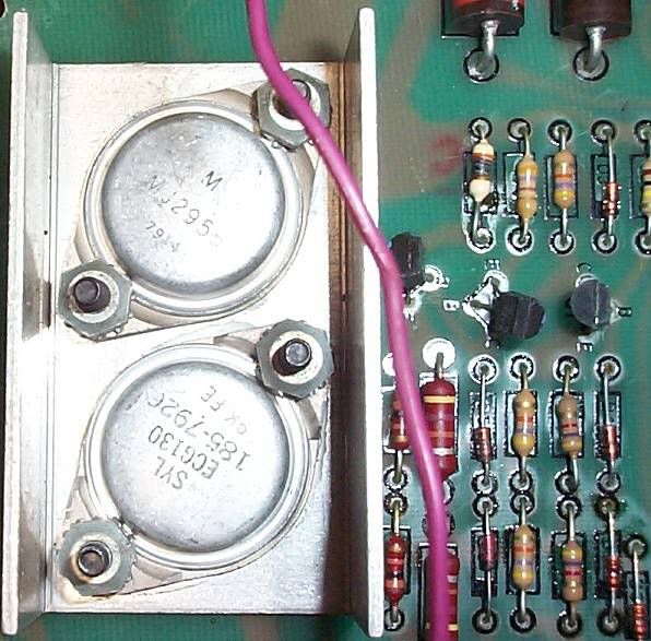
The output transistors and heat sink. Yes, the transistors are original and still working fine and I won't be replacing them. Notice the 7914 and 7926 dates.

They are mounted to the heat sink with screws on the bottom side of the board and secured with nuts. As discussed above, they are not insulated from the heat sink with mica, but do use heat sink compound. The heat sink does carry the "mid-point" 30 volts and of course is not grounded. The purple wire is one of the speaker connections.

I calculate the radiating area of the heat sink to be roughly 12 1/2 square inches. Seems a bit on the small side, even for 25 watts. It does get warm to the touch during operation. When mounted in the case the heat sink is quite close to the speaker, so one possibility is that speaker movement helps in cooling. With the exception of a 2 1/2 inch square hole cut in the back panel and covered on the inside with grille cloth, the amp is pretty much sealed when fully assembled.


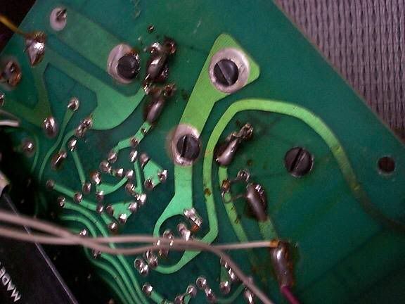
This is the trace area of the board underneath the heat sink. No sockets. The emitters and base are connected with wire wrapped around the pins and the other end laying on a trace, both ends soldered of course. There are quite a few other connections made with wire soldered to the top of traces.

The trace under the screw to the upper left connects to the output capacitor (C20). This cap, as well as C21 are 35 volt caps. I replaced them with 75 volt units just because it was easy to do since I had the board out anyway (and it is a real pain to get the board out).

While there are definitely some improvements that could be made in the construction quality of this amp, it has proven itself over time to be very reliable and good sounding. Chalk it all up to very good luck, but it's not just "my opinion".

http://reviews.harmony-central.com/reviews/Guitar+Amp/product/Electro-Harmonix/Mike+Matthews+Dirt+Road+Special+112+Combo/10/1

As for the IC, I decided I liked the TL072 better than the 4558. Not any real difference in tone, or distortion or anything like that.The 4558 wasn't really hissssssy, but the TL072 was noticeably quieter.
#27
A picture might help. There were several different versions of the standard. I thought all of them had a master volume/gain control but I could easily be mistaken.
#28
Schematics and Layouts / Re: 60W Power amplifier
August 13, 2007, 07:34:56 PM
Quote
But I think you have a problem there. First, you don't know me, and so making the leap that I'm blinded by anything, even delusion, into a love of complexity shows that you're babbling again. Fact is, the simple overcurrent clamp is very, very difficult to improve on for short circuit protection.

You have the problem R.G. You even point it out:

Quote
I don't have a solution to protecting from shorts that is simpler. And I don't have a solution to protecting from short circuits while not affecting the sound.

I think, in fact, that we can logically prove that's impossible. If an output is shorted, there is no sound, by definition. The short has seen to that. So once the short starts, sound ceases. What short circuit protection does is keep the amp from dying during the duration of the silence.

Your love of complexity as a virtue is so great you are so obviously blinded to anything that threatens to take that beloved complexity away from you.

Of course there is no sound during a short, but I seriously don't get how that proves there is no simpler solution. All you proved is you can't see one.

Maybe one day someone will give you one with permission to use it.

QuoteAnd this points up another issue with your argument. You do not realize that short circuit protection and safe area protection are not the same thing. I deliberately didn't correct that gap in your background for a few posts now.

Sorry, but you rattle on about nothing too long to waste space reproducing it for you. But - ok, assume I don't.

A glichy sound by any name is still a glichy sound.

QuoteSo let's go with question #2: Do you believe that there are situations where safe-area protection can prevent your amp from dying? Again, please try to limit yourself to yes or no. I noticed you were unsuccessful last time, just as I predicted. I'm guessing you'll do a LOT of dancing to avoid saying yes or no to this one.

"Yes", there are some situations where what you are calling "safe-area protection" can prevent an amp from dying.

But that does not imply that what you are calling "safe-area protection" is necessary or desirable in all cases.

What you are calling "safe-area protection" isn't because it only monitors one of the variables. Current limiting would be more accurate.

And you can say I was unsuccessful again, but the problem is with the hidden assumptions of your question. Qualify those assumptions and I have no problem with a yes or no answer.

Quote
What is your training and experience in analyzing power electronics for reliabilty? Is it just using them until they break or don't break yet?

Yes. Reality is fact - theory isn't. If it doesn't break in use, then it is reliable. Bridges built only on theory do fall down, and in doing so, theory changes.

I doubt it, but you may have heard the saying: "when reality conflicts with theory, develop another theory".

Quote
So given that you will INVOLUNTARILY be forced to crash into a brick wall, which one do you want, the model T or the modern vehicle.

I will never be INVOLUNTARILY forced to short the output of my amp. That is just one of your hidden assumptions.

The rule about plugging in the speaker before turning the amp on pertains equally to solid state - you won't short the output by plugging in the cable. Deny that one.

And common sense tells me not to use a long speaker cable, so it's physically impossible for it to be run over.

Quote
There is no designing FOR tone and NOT FOR protection (again noting that "short circuit" has nothing to do with it, see above again). The two are not antagonistic concepts.

It may be possible that you see them as antagonistic because to you "tone" only happens on the edge of circuit failure. If that's the unstated condition in your mind, you need to do some more thinking.

I don't have a clue what tangent this is. No, tone doesn't happen only on the edge of failure. But with your mandatory protections, tone doesn't happen.

Again, since you keep avoiding the question, why don't you recommend these things for tube amps? Wouldn't having them produce a nice glichy sound be equally "great amplifier design?"

QuoteThat's correct. How do you define doing your job? Do you want to damn the engineer for wanting the job, the company for wanting to make a profit (which, if you'll think it through, is the only reason you can have any amplifier at all), or both of them for not asking you first? At which of these stops do you get off?

Thank you... I had a feeling you only do as you are told.

Quote
So you're a member of the maverick herd, who pride themselves on not being in a herd, and all uniformly going their uniformly separate ways, right?  ;D

I love it - rebel without a clue.

Actually rebels are quite different. Herd members don't mind them as much as mavericks as rebels are just as easily controlled. But of course I wouldn't expect a herd member like yourself to understand the difference.

Quote
Nobody ever said that all amps without protection died instantly. I certainly didn't.

No, you just call them "unreliable" with nothing to back up the claim other than intentional destruction or some unlikely accident.

Quote
So - how many others of those you got? They're kinda rare, aren't they? Not a whole lot of them survived?   :)

Only the one. I don't think they are that rare. Most people like them too much to give them up. Ever played one?
#29
Schematics and Layouts / Re: 60W Power amplifier
August 12, 2007, 12:35:26 PM

I have no problems understanding how short circuit protection works and have no doubt that it will prevent excessive current flow during a short of the output.

But you're missing my point - obviously blinded by the delusion that more complexity makes you a better engineer. I'm sure you can recommend much simpler alternatives to solve the "problem" of the user shorting the output of an SS amp - without affecting the sound while providing protection. And I'm just as sure you have a "technically superior" reason why they won't work as well as those that do affect the sound.

Just like the only real reason to call a transformer driven totem pole design "unreliable" is to claim that it is an old design and not technically superior to modern designs. A reason that could equally apply to any tube design if there wasn't a bias for simpler tube designs (pun intended) to provide better sound.

Kind of like claiming a model T Ford is unreliable because it wouldn't survive a crash into a brick wall as well as a modern vehicle. The obvious solution is "don't do that!!"

Suppose you came up with a novel circuit for a tube amp. It offered all sorts of technical benefits - longer tube life, better linearity, faster slew rate, and even open output secondary protection. The trade off is of course that as the user started pushing for power tube distortion, the sound would get glitchy and if they insisted on pushing it harder, the amp would shut itself off.

Would it sell? Of course not. Despite all of the technically superior reasons, no one would buy one, or if they did they would return it pretty quickly once the problem with the sound was discovered. Fender's technically superior improvements to eliminate that "awful distortion" during the silverface era is a good example.

Maybe a corporate engineer would lose his job by designing an SS amp for tone instead of short circuit protection "just in case". After all, the corporate machine couldn't save money by using cheaper devices, couldn't downgrade the construction, and the amp might not make it through the warranty period before failing. The engineer also wouldn't be living up to his job description by failing to be "able to design and implement complex circuits that meet or exceed all specified cost constraints". Definite reasons for being fired - no doubt.

Herd members in "good standing" just simply don't like mavericks - mavericks interfere with their erroneous and delusional perceptions about themselves.

But despite your well justified reasons to help protect my amp from me (and all I have to do is give up on good sound making another myth true); there are plenty of vintage SS amps out there, without short circuit protection, still providing great sound despite any opinion of unreliability by you.

That sir is a FACT - but one you will deny cause I can't give you an all inclusive list of all the well satisfied users? Even if I could, you would just chalk it up to a collection of opinions and not a "technical justification" - only because it doesn't match your opinion. You only accept hearsay as fact when it matches your opinion.

I picked up one this weekend - for only $25 bucks. An EH dirt road special (now I don't have to build my own). I couldn't believe it and it was all an accident. It was in a pawn shop, in great cosmetic condition and the only problem was it didn't work. Only a faint hum sound when it was turned on. The guy at the store claimed his electronics tech estimated a $200 repair bill minimum and he just wanted to get rid of it.

About 5 minutes of debugging found the problem. No, it wasn't the output transistors or anything in the power amp section. Since I'll have to remove the board to replace the defective component, I'll post a picture of the output transistors and the heat sink - you'll just love it. Yes, despite no short circuit protection of any kind (I posted a schematic in another thread), AND it still has the original 1979 vintage output transistors.

The problem is the 4558 opamp in the preamplifier. The second side (pins 5,6,7) is hosed. It's run off a single polarity +15 supply with the non-inverting input biased at half. I get 7 1/2 volts at that input, but only 2 volts at the output and inverting input.

Don't these things have protection circuitry? Oh well, I guess it DID survive roughly 28 years with it.
#30
Schematics and Layouts / Re: 60W Power amplifier
August 09, 2007, 04:23:44 PM

Hmm... yeah, maybe I'm lumping too much under the general term "protection circuit". It's the short circuit protection I primarily don't find very toneful.

The Acoustic 260 doesn't have it, the 361 did.

The Sunn Beta (or Alpha, same power amp) does sound ugly once the power amp is overdriven. Never played a Coliseum. I'd include the Concerts in the simple-without classification.

Not really familiar with the other amps you mentioned. I did have a late 60's Standel that I wish I never gotten rid of, but I just couldn't move it as well as other things.

Ok, answer me this: What is it about the transformer driven totem pole topology that makes it unreliable? Fine, it usually doesn't have protection circuitry, but does that make the topology "inherently" unreliable? Is it the transformer?

Maybe unreliable in the case of a direct short to the outputs, but if you don't do that - I haven't seen them fail under "abusive playing situations" with the exception of some with underrated output transistors - but that would be a misapplication of component, not the fault of the topology.

Everybody tells me they are unreliable, so I just want to know what makes them that way - other than "they are old design, not modern technology".

Tube circuits are even older... but what were those tube amps that used a transformer drive by Fender? PS somethings? I saw a schematic once and almost died laughing.