Menu

Show posts

This section allows you to view all posts made by this member. Note that you can only see posts made in areas you currently have access to.

Show posts Menu

Messages - j_flanders

#1
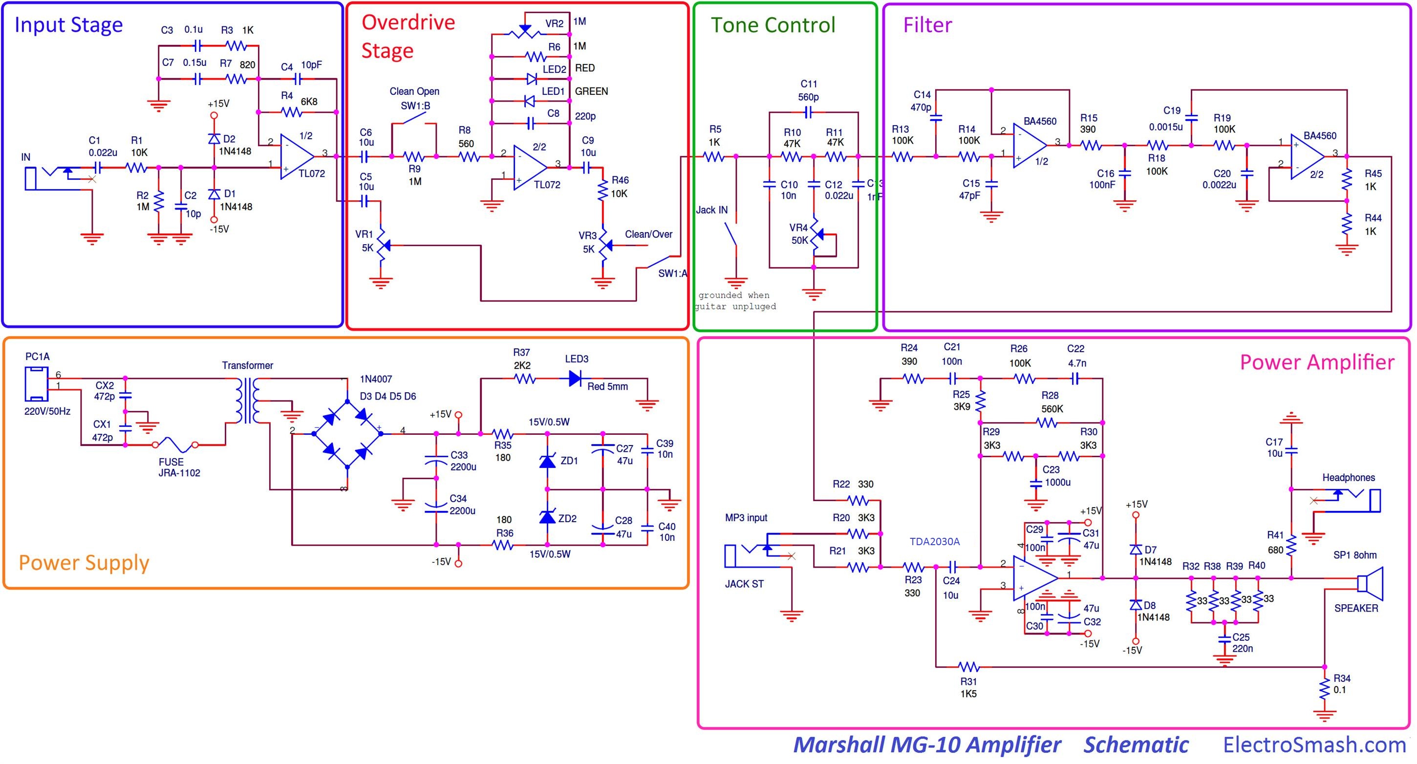
In case anyone wants to tinker with a simulation of the circuit, here's a link for an online app (http://www.falstad.com)

Preamp section frequency response (no option for adding clipping diodes, or log type pots):
https://tinyurl.com/ybvl5aod

Power amp section (no idea how to include the speaker (inductor?) in the current feedback loop. I just used an 8 Ohm resistor.)
BTW, the spec sheet says typical gain of around 26, but this seems to have way more. Anyway, I don't understand a lot of what they did there and haven't found any other examples of using this power amp in inverting config.
https://tinyurl.com/ycu5denz

You need to have the Java plugin active in your browser.

Some screenshots below.
#2
Thanks for the suggestions Phatt. I tried some of those previously. Slightly revoicing the amp towards less gain and less treble won't be a big problem I think. But I will keep them in mind.

For now I've given up on the hiss. Maybe attenuating some high frequencies in the revoicing process will cure some of that.

At the moment the volume control is my biggest issue.

To track down the 'crosstalk issue' which is part of that problem I did and discovered the following:
1)Recorded some guitar playing into a looper and hooked it up to the guitar input of the amp.
2)Set my DMM to VAC and checked every point along the signal path.
Results:
I see fluctuating voltage (corresponding to the playing looper) up until the leg of volume pots (both clean and OD channel).
I see 0 Vac on the wipers because the volume knobs are on zero and thus wipers are connected to ground.
After the wipers all the points along the signal path show 0 ac voltage until I arrive at R32, the first resistor of the Zobel network, right before the speaker. That is the first point in the signal path where I see a small ac voltage again and it corresponds to my playing looper.
I did skip some caps when testing because I was following the path at the component side and the legs of those box caps aren't accessible there.
I removed opamp2 (in the filter section) from its socket. There is still sound coming from the speaker but it's quieter (even though I saw 0 volts ac on out1 and out2 when the opamp was in circuit)
I have no idea what's going on here!

Now for the volume pot problem it gets even weirder.
One of the things I tried in getting more usable range from the volume control was to insert a 100k pot in series right before the volume pot (after R46 10k).
I realise this changes the load for the opamp and will probably also affect the contour control coming right after that.
Now for the weird thing:
Previously I had this trebly sound with the volume knob on 0 and a contour control that didn't affect it when turned.
Now I experience the same thing but with the volme control on 1 or 2.
So I'm back where I started: having to turn up the volume control to get a 'normal' sound, which is then too loud.
I also noticed the sound gets bassier the more I turn up the volume pot. And the trebblier the more I turn it down, until I get to 0 and then there's only treble left...

So, please help me out here. Where do I insert a voltage divider that gives me more range on my volume knob?
I could place it after the tone stack but it would interfere with the input resistors of those Sallen key Filters.
I could place it right before the power amp but there it woud interfere with the input resistors of the power amp.

Is a buffered volume control the only way here? What else can I do?

#3
PCB tracing. (scroll to the right for the preamp section)
#4
Quote from: Enzo on June 28, 2018, 05:51:19 PM
Crosstalk is radiated for the most part, it isn't about continuity.
Ok, I stopped lifting components after those two as I was afraid this was going to be the case and that I'd do more harm than good, eventually lifting traces rather than legs.

Quote from: Enzo on June 28, 2018, 05:51:19 PM
Is this a real problem?  I mean when you are on clean and PLAYING, does this dirt channel bleed interfere?
No, it's not a real problem. It does not bleed through. I just thought it might be related to the hiss which I find rather problematic.

Quote from: Enzo on June 28, 2018, 05:51:19 PM
But with that socket empty is the hiss still there or is it now gone.
There's a tiny amount of hiss left but it's negligible and normal.
No sound, so the crosstalk happens in the preamp section, not in the power amp section.

Quote from: Enzo on June 28, 2018, 05:51:19 PM
Does the contour control affect the tone of the hiss?
It does not affect the hiss. It does not affect the tone of the radiated sound (which is very trebly, lacking all bass)

Quote from: Enzo on June 28, 2018, 05:51:19 PM
How to isolate it?  A scope or signal tracer is good, step along the circuit. 
COnnect a clip wire to ground and use it to ground the signal path anywhere that has no DC on it.  Does grounding R18 kill hiss?  R13?  R10?
If you are loathe to shunt circuit directly to ground, add a cap, like a 0.1uf or a 0.047uf in series with your ground wire.  That will shunt signal to ground without creating a DC path.
Crosstalk?  You can use similar tests to locate where the signal is re-entering the signal path.

Thanks, I'm going to try that tomorrow.

In the mean time I traced the PCB to see if there could perhaps be a mistake, but as expected there wasn't any. It might still show where the radiation could be occuring I guess.
I'll post it below, it's rather big.

Another thing I noticed is that the component leads were bent and then soldered. In many places those snipped of and bent leads are right on top of and touching the neighbouring traces. For all I know they might even have protruded, though so far the continuity tester says no.
This seems like a good way to radiate? Is it worth the effort to snip them all off, a lot shorter? Here is a picture to show what I mean:


I guess the real problem is that this amp is too loud. It's actually loud enough with the volume on 0, it's just that it's all treble then. The tiniest amount above that and it gets too loud but sounds normal. I just need way more range on the volume knob.

Can you suggest some solution for this. I could go ahead and insert some voltage divider here or there but isn't that going to mess up input or output impedances of certain sections, or affecting the frequency response of the tonestack or those filters.

I already tried a lot of things:
1) Double r46 to 20k
2) Lower the 5k volume pot value by putting a 1k or 2k resistor parallel to it
3) Replace the clipping LEDS (1.8Vf) by 1N4148 (0,7Vf) and because of the lower clipping threshold I raised R8 to 5K and replace R4 with a 5k pot to have less (treble) boost.
4)Connect a cabinet to the headphones output. The current limiting resistor is probably rated for 16Ohm headphones rather than 8Ohm speakers but they must have taken 8Ohm HP into a account. It hasn't burnt through. It was too muffled sounding so I changed c17 to a NP 6uF cap.

But I would still like to have a simple voltage divider somewhere that does not affect the voicing.

Thanks for your time and your suggestions Enzo!
#5
Thanks for the quick reply Enzo. It was middle of the night so I had to wait until now to try your suggestion.

I replaced the 4560 with a socket and tried a couple of different opamps in there. There was no difference in noise.
Your remark about crosstalk got me thinking that somehow perhaps the noise of the OD channel finds it way through even when nothing plugged in.

I lifted one leg of R46, the 10k resistor that is connected to the volume pot.
Surprise: even when breaking the connection between R46 and the volume pot there is sound coming through.
It sounds the same as when having the volume pot on 0.
I also lifted the negative leg of c10. Same result.
Obviously the volume pot no longer works and it seems the tone control is bypassed as well, at least I can't hear a difference when turning left or right.

Removing the Sallen Key opamp gives no sound, so it isn't finding its way directly to the power amp.

How do I figure out where or how 'it' finds its way?
Do I simply check for continuity between any of the components in the NFB and components after the tone stack? I think my DMM has 50 Ohms as a limit for a continuity beep. (if that matters)

Do I start lifting legs that are connected to the output pin?

Check for AC on components after the disconnected volume pot and work my way back?

I already check with a strong backlight and a magnifying glass for solder or trace bridges on the pcb side and on the component side.
#6
I bought a used Marshall MG10CD... yeah, I know.
I guess it's one of those pieces of gear, like a DS1 or Metal Zone, that you need to have owned to understand all the hate.  <3)
I have found the "10" stands for: needs 10x less gain, 10x less treble, 10x less output and 10x less hiss.  :duh
I'm planning to mod it and turn it into a head with a Celestion fitted cab but I need to tackle some issues first.

Problem 1: hisssssssssssss
I can probably fix the gain and treble/voicing issues but I'm really struggling to figure out where the hiss (white noise, not hum) comes from. I see other MG owners complain about the exact same issue.
I understand that with lots of gain, there will be hiss but the problem is that even with nothing plugged in, there's quite a lot of hiss. With no gain other than coming from the power amp I don't understand where this hiss comes from.
At the levels I'm playing, turning up the gain to 10 only adds hum, and pretty much no extra hiss.

There's a pretty good analysis and nice schematic of this amp here: https://www.electrosmash.com/marshall-mg10
But unfortunately he made some mistakes when tracing, especially in the tone stack and Sallen Key sections, so the frequency plots are wrong.
R18 and R19 are 10k instead of the 100k in the schematic and he's missing R12 47k to ground right before R13

Link to the schematic in case the horizontal scroll bothers you:
https://www.electrosmash.com/images/tech/mg10/marshall-mg10-schematic-parts-big.jpg


Here's the only correct schematic I have found:
Link to the schematic in case the horizontal scroll bothers you:
http://oi63.tinypic.com/eqrqm1.jpg


With nothing plugged in, the preamp section is muted right before the tone stack, so turning gain and volume controls do not affect it.
If I ground the circuit right before the power amp (R22) the hiss is completely gone.
So, it must come from either the tone stack or those Sallen key filters.
If I bypass/jumper R15 and thereby disable that passive LP filter, the hiss is brighter but not louder so I think I can narrow it down to the tone stack or that first Sallen key filter.
Any suggestions on what to try next? Or any ideas on what could cause the hiss in that part of the circuit?

I have a Vox Pathfinder10 and you can honestly not tell if this amp is on or not when nothing is plugged in. Even with my ear against the grill cloth, one inch away from the speaker I still cannot tell if it's on. So it must be possible to have a dead quiet amp with nothing plugged in. And this amp is pretty bright as well and mutes/grounds the circuit in a similar spot.


Problem 2: OD channel volume knob mystery:
Another issue I can't seem to figure out is the following: on the OD channel, with the volume knob on 0 there is still some sound coming through. It's all treble frequencies, no bass.
When I ever so slightly turn the volume knob, like 1/10th of a mm, the bass frequencies kick in and the sound seems normal but it's actually already too loud by then.
I measured the resistance between wiper and ground to make sure there's no 'residual' resistance left when on '0' and it measures to about 1 Ohm.
One Ohm would give me 1/15000 of the maximum output (load of 10k + 5k pot). Maximum output of that opamp is about 2V because of the clipping leds in the NFB so output from the volume voltage divider would be 0.00013 volts. Can I hear that after the power amp amplified it? How would it explain the missing bass frequencies?
#7
Thanks for the replies!

Quote from: Enzo on January 30, 2018, 12:37:26 PM
I am pretty sure they design their own, because it is something any engineer can do on a napkin in  bar.  They do not need help for these most basic things.  They all look the same because they all do the same job. Sure there might be times when some offshore place has something ready to fly, and they snatch it up.  But do to the simplicity of these things, they are just as likely to say to their offshore plant team, "throw us together a basic practice amp."  And so you get some odd drawing signed by Wing Wang.
OK, I wasn't implying that they need help. Quite the opposite, that they maybe simply wouldn't bother.
I didn't even consider the possibility that all those companies (Marshall, Fender, Vox, Orange, Kustom, Artec, Laney, Danelectro, Randall etc etc. ) had their own plant for producing these ss amps.
It's probably my wrong assumption but I thought all these amps came from the same (couple of) factories. Kinda like a Cort or Samick factory but for ss amps. Given that idea and the peculiar similarities I wondered if they would perhaps not even bother designing these circuits themselves. Hence the topic.

Quote from: Enzo on January 30, 2018, 12:37:26 PM
Something else to consider is that these products are aimed at a market niche.  And all the competing basic models compete for those same niches.  Mesa doesn't sell bottom end amps.  They don't market to that niche.  Whether you like them or not, Mesa markets as a higher end brand.  An Acura rather than a Honda, so to speak.

Maybe burgers is a better simile.  You have fast food burgers, which include a dollar menu choice.  Then there are fancy burger places like Red Robin or even Dennys or your local bar.  None of those places offers a dollar menu.

But look at those dollar burgers.  All have a same size hunk of cheap beef, all have mustard and ketchup squirted on, all have a square of sliced cheese.  And all come with a little bag of small cut fries with loads of salt.
Yeah, I understand but still, I always thought Mesa is the odd one out.
Ask some non guitar playing but guitar music loving guys to name some amps and the list would probably be:
Marshall, Fender, Vox, Orange and Mesa. That would include Mesa in the list of the big 5 (don't know about Ampeg)
None would say Friedman, Ceriatone, Dr Z or so, since you're talking higher end.
And, while 1 dollar meal places might not serve a 25$ wagyu beef burger, and Red Robin doesn't sell a 1$ burger, Marshall and Orange do in fact have amps in the same upper price range as Mesa. But you made a point about it being/wanting to be high end only.

Quote from: Enzo on January 30, 2018, 12:37:26 PM
Clipping across the signal path or across the gain stage isn't all that different to me.  Your pair of penny diodes is in either.
If you apply insane amounts of gain you'll end up with a square wave which sounds the same no matter what clipping circuit created it.
But at lower levels of clipping however, I thought there was a fundamental difference between:
- diodes in the feedback loop of a non-inverting opamp
and
- clipping to ground or in the feedback loop of an inverting opamp

Inverting feedback or to ground:


Non inverting feedback:


To my ears, having part of the original mixed in (diodes in non inverting feedback) sounds very different from simply having the tops clipped or rounded.
#8
When you compare the circuit of a Tube Screamer, a Fuzz Face, a Rat and a Big Muff they look like coming from different planets, while if you compare the schematics of those cheap SS amps from the big names (Frontman, Pathfinder, MG, Crush etc.) they look like they came from the same house.

So, I wonder if those companies actually design these little practice amps each themselves or if they are designed by the same 'foreign entity'?

To counter some expected responses:
I do realize that I picked very specific pedals and that a lot of other pedals are very similar to each other.
I do realize that a honky, ratty or fuzzy pedal is for a 'niche target audience' while guitar amps are intended to suit as many players taste as possible.
I do realize there are only so many ways to design an amp, a tone stack, that all of them deal with the same guitar frequencies and all will want to produce as cheaply as possible resulting in a similar choice of values for resistors and caps and other components.
I also realize that both in pedals and amps, people/companies do borrow/steal ideas from each other.

Yet still, the similarities between a lot of those 'cheap mass produced big name ss amps' is striking. And so far, not a single one seems to stand out or do things differently enough to say: hah!.
They all use the same opamps. Fender isn't saying: we'll go with a ne5532 instead of the usual 4558 and our amp will be 1$ more expensive. It's not as if a Fender fan will buy a Marshall MG instead of a Frontman because it's 68$ instead of 69$.
Across those amps they all seem to be using the same few mechanisms for their 'dual channel' switching (see links and examples below)
Another thing that is 'suspect' is that the evolution/iterations of the models of these amp are the same across those brands:
At one time they used transistors, but when they switched to opamps, they all did so.
At one time all of them came with a real analog spring reverb (Frontman 15R, Lead 12R, Pathfinder 15R, crush 15R etc.) and when these (crappy) spring reverbs were left out in a new iteration of these amps, then all brands did so. Not a single one said: we'll keep it.
As far as I can tell they all come with speakers from the same manufacturer (Chunil speakers)

Obviously, they don't build these amps themselves but outsource it to some Far East factory.
So, how does this work? Anyone some inside info on this?
Does a Chinese 'designer' let Fender, Vox, Marshall etc. choose from modules (booster, clipper, tonestack etc)?
Do they get a list with available components and a rough total of components they can use and completely design it in house?
Do they get complete (prototype) designs which they can only fine tune and put their designer's name under it.
Or do they simply order a 'fender sounding' 'Vox sounding' amp and actually don't really care and have little to no input on the circuit design?

Here are some random examples of similarities between schematics where I'm thinking: what a coincidence...

Epiphone Studio 10 vs Vox Pathfinder 15:
http://archive.gibson.com/Files/schematics/Studio%2010.jpg
http://www.tdpri.com/media/vox-pathfinder-15r-schematic.27215/full?d=1349532940
Both using a pot to change feedback resistor of the first non inverting opamp and the input resistor of the second inverting opamp at the same time.
Clipping diodes always in the signal but '(de)activated' by a boost switch (operated through a FET) to '(de)activate' some some parallel resistance in the feedback of the second opamp.

Marshall valvestate 10 vs Vox Pathfinder 10
https://elektrotanya.com/PREVIEWS/63463243/23432455/marshall/marshall_valvestate10_10w_8001_8010.pdf_1.png
http://bencraven.com/wordpress/wp-content/uploads/2016/07/20160528_vox-pathfinder-10-schematic-1024x400.gif
The other way to boost and clip. This time diodes are switched into the signal while at the same time some resistance in the first non-inverting opamp is connected/shunted to ground.

Frontman 15G vs Marshall MG
http://blueguitar.org/new/schem/fender/frontman15g.gif
https://www.electrosmash.com/images/tech/mg10/marshall-mg10-schematic-parts-big.jpg
The third way: bypass the clipping section entirely and as coincidence would have it both use the same type of contour/tone/filter.

I'm not saying all these amps sound the same, far from it, but that a lot of them look like they were designed by the same person.
Maybe I'm looking too much into this or focusing on some peculiar but perfectly explainable similarities but I'd like to hear what people's thoughts on this are.

Are you 'naive' and wishful thinking like me and secretly hoping that even that Pathfinder you love so much was designed by someone at Vox that had Vox tones running through his veins and gave everything he got to capture the legendary signature sound of his company/brand in this little cheap ss amp?
Or do you think it breaths as much Vox as a Joyo ACtone: Chinese crap that happens to sound good but nothing to get emotionally attached to.

Also, why is there no Mesa 15G ? They seem to be the only 'big name' in this that does not take part in the 'cheap ss practice amp' field.

And as a last note: why do all of them, as far as I've seen, clip to ground (or the inverting pin which boils down to the same thing) and none seem to do the 'non-inverting feedback clipping'.
Clipping to ground, especially with higher supply voltages than the pedalwise 9V, does provide for a little more dynamics but at the same time especially with those small cheap speakers it gives fizzy, crackly note decay at edge of break up settings and 'bees in a can' for higher gain settings. This is what people associate ss pratice amps with and with feedback clipping you'd have none of that.


#9
Amplifier Discussion / Re: Vox Pathfinder 10 mods
January 30, 2018, 06:59:44 AM
Quote from: blackcorvo on January 27, 2018, 03:15:10 PM
So, what these mods have done for me:
- Changed C6 from 220n to 470n to up the bass response a bit
Must be only a tiny bit as C6 (220nF) is in series with C5 (4,7nF).
Caps in series are like resistors in parallel, so the total capacitance of stock C6 and C5 is 4,601nF.
Changing C6 from 220nF to 470nF would result in 4,653nF, a change of 53pF or a 1% increase...

Now, C5 is in parallel with the upper part of the gain pot, so in reality things are a bit more complex and variable:
When the gain pot is maxed at 10, C5 is effectively shorted and only C6 is active. Turning down the gain slowly brings C5 into play, putting it in series with C6, lowering the capacitance, increasing the low cut / high boost.

Your mod will have most effect when gain is high and least effect when gain is low.

Changing C5 instead of C6 could give you more reach/control at lower gain settings because stock, it is a much lower value than C6.

Quote from: blackcorvo on January 27, 2018, 03:15:10 PM
Removed the Red LEDs from the board and placed 2x White LEDs soldered directly onto R7, for a less harsh distortion even on "clean";
It's still 'hard clipping' to ground, as these go to the inverting pin, but since they are in parallel with the feedback resistor R7 and cap C7, I do agree that it sounds a little less harsh. They will clip in clean mode, but you will have to turn up the gain considerably and by then you're also bosting lows a lot more, resulting in a flatter pre-clipping frequency response, which is a large part of the reason it sounds less harsh, more balanced.

Those green wires soldered to the back of the board you see on the PCB tracing picture was a similar mod, me trying different diodes, resistors and caps in the feedback loop.
#10
Amplifier Discussion / Re: Vox Pathfinder 10 mods
January 30, 2018, 05:41:43 AM
Here's the correct schematic by the way. (Edit: Sorry about the large pictures. There's a scrollbar at the bottom of the post to see the right most part of them.)
Green means 'correct component value', red arrow means 'the component was in the wrong place' or 'incorrectly connected'.

One correction not included is about the note: "Gain switch shown in Clean position"
The schematic shows one part of the switch in clean position, namely the diodes taken out of the circuit, but the other part shows it in distorted position, namely R4, which should not be connected to ground for Clean.


Here's the circuit board tracing.
Red is signal, black is ground, grey is power supply to opamps. White components are resistors, greens are capacitors.
I was only interested in the preamp section, so I stopped at C19, just before the power amp section.


I love this little amp. I've been playing it daily (nightly actually) for the past two years or so.
The clean channel is perfect, the overdrive channel not so much. I tried a ton of mods all over the preamp section. I'll post about them later on.