Menu

Show posts

This section allows you to view all posts made by this member. Note that you can only see posts made in areas you currently have access to.

Show posts Menu

Messages - KMG

#121
I work for a leading engineer in the development department of Mega-Milas Ltd. We develop a fire alarm systems, information systems and surveillance systems mainly for railway transport.
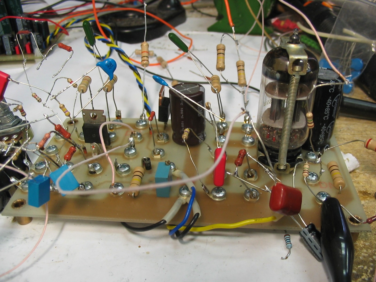
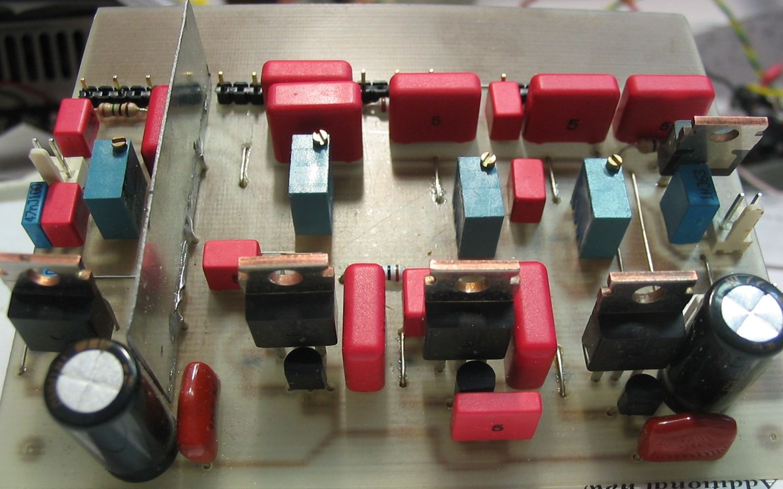
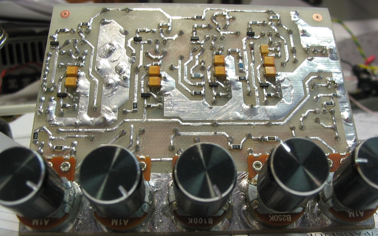
For example, one of my designs - PCB (multilayer) for the fire alarm server for railway train.
#122
QuoteYou used an emitter follower to buffer the bias voltage on the FET source. Is the temperature coefficient of Vbe a problem there? Or does it actually improve stability of the circuit? Likewise for the tempco of the germanium diode.
I did not notice any problem with temperature stability.
QuoteSo do you think a Schottky would do instead of a germanium diode?
No details of the curves for diodes at currents around 1 mA.
So it needs testing.
QuoteKMG - any chance you can repost the schematic and/or pictures? I can't load the files in the original post.  Cheers
I Think that is a problem of internet service providers.
Do you see my web page?
http://milas.spb.ru/~kmg/index_en.html
Anyway, there you can download project archive:
http://www.megaupload.com/?d=U2E5TY54
#123
Quotewhat i was trying to say is that, with those "sacred values", i knew where they went and what to change, add some caps and do some mod (caswell, levi, etc). But now i'm lost. I don't recognize anything. What i *DO* know is that KMG is doing a great job at emulating tube sound. I have his website on my bookmarks and I was mesmerized 'bout his results long before I posted my question about his SS poweramps at this forum (today a posted another question at freestompboxes forum).

I know those values aren't sacred, but that was what i was used to (and I don't like ch-ch-ch-ch-changes)
These "sacred values" are suitable for given preamplifier when using the same tubes. For example if you replace tube on Russian 6Н2П-ЕВ these values will be different for prorer sound.
V/A curves of FETs differs significantly from the tube ones.
If you connect a bypass capacitor directly to the source of the FET, increase of gain will be too large.
You`ll get different frequency response of preamp stage.
#124
Each stage of preamplifiers was designed with the help of this "test equipment".

Right part is the tube version of the stage with input and output interstage circuits.
At the FET part, I first set up the gain below the cathode circuit cutoff frequency of the tube stage by adjusting the resistor at the FET source (adjusting biasing voltage at the same time to keep operating point).
After this I added a correcting RC circuit at the FET source to adjust gain above  the cathode circuit cutoff frequency of the tube stage. R define gain, RC define cutoff frequency.
Frequency response i checked by "RightMark Audio Analyzer".
Thats why you don`t see original values of components in source networks.
The last thing I adjusted the parameters of the "scalable diode" part to provide adequate "grid" limitation.
#125
Tubes and Hybrids / Re: LND150 tube emulator attempt.
February 04, 2011, 11:37:00 AM
At the first waveform can be seen that the FET cut-off "sharper" than the tube. I solved this problem by placing GE diodes in the source of FET.
There is no information in LND150 datasheet about gate-source protective zener. Negative half-wave may exceed maximum gate-source voltage specification.
#126
Two short samples with tube screamer in front (at first part of each file TS is bypassed for reference)
Neck
http://milas.spb.ru/~kmg/files/projects/slp/reamp/BoostNeck.mp3
Bridge
http://milas.spb.ru/~kmg/files/projects/slp/reamp/BoostBridge.mp3
#127
QuotePerhaps can you post some sample sound of it?
At this point still only reamping samples
Clean 9.9M
http://milas.spb.ru/~kmg/files/projects/slp/reamp/Clean.mp3
Clean wih DRE AL3201 (hardwood studio effect) 10.0M
http://milas.spb.ru/~kmg/files/projects/slp/reamp/CleanR.mp3
Drive 12.6M
http://milas.spb.ru/~kmg/files/projects/slp/reamp/Drive.mp3
#128
QuoteI managed to get some samples recently, but I've not tried them yet.
While waiting you can try them in simulator, SPICE models you can download there
http://www.supertex.com/spice_models.html
#129
QuoteI messed around with arrangements of multiple FETs, but the dual gate MOSFET made the most sense. They are still widely available, sadly in tiny SMT packages.
These dual-gate MOSFETs is mainly targeted at the AGC control in the RF-frontend and work with a very low scale input voltage.
Now I`m looking at this high voltage N-channel depletion mode (normally-on)  lateral MOSFET.
http://www.supertex.com/pdf/datasheets/LND150.pdf
#130
Accurate emulation of grid current often means more than a shape of clipping.
Look how tube stage respond on "burst" input signal.


K1 - Anode voltage
K2 - Input voltage
K3 - Grid voltage
K4 - Cathode voltage
Output signal  "floats" in time at a constant input level.
Average current varies almost 2 times.
Amount of changes depends on interstage circuitry (impedance, time constant etc).
That's why guitar players often say that tube sound "live" and the sound of semiconductors "dead" (uniform).
This refers not to the color of harmonics but to reaction on the sound picking.
#131
QuoteHow is the temperature stability of your FET building block?
Right now I did some tests. I used a soldering iron to heat the flange of the transistor up to 70 ° C. Changing of static drain voltage in range from 20 ° C to 70 ° C was 4-6 V (for different stages). It`s about 3-5% of change.
"Don`t worry, be happy" ;)
#133
Schematics (pdf)

Stage by stage frequency response in comparison with the original tube version


Ready to transfer PCB (pdf)

Upper side assembly (pdf)

Bottom side assembly (pdf)


Sample (gain control only by volume knob on gutar)
#134
Preamps and Effects / Re: V30 speaker simulator
February 01, 2011, 04:37:36 AM
There you can compare reamping samples recorded via 4x12 cabinet & V30 simulator:
http://www.ssguitar.com/index.php?topic=2007.msg12962#msg12962
#135
The tone stack output (J5.3) signal is first fed to the buffer stage (Q11) & after scaling down goes to the preamp output (J6). This preamp output is connected to loop.
I never use signal from tone stack to drive high capacitance loads.