
IT LIVES!!
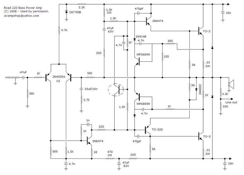
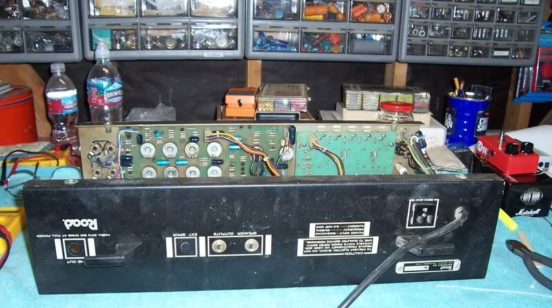
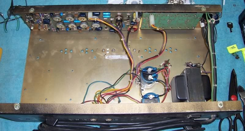
Here is my final schematic with mods for the Road Electronics amp. Got it fired up today and it sounds fine.
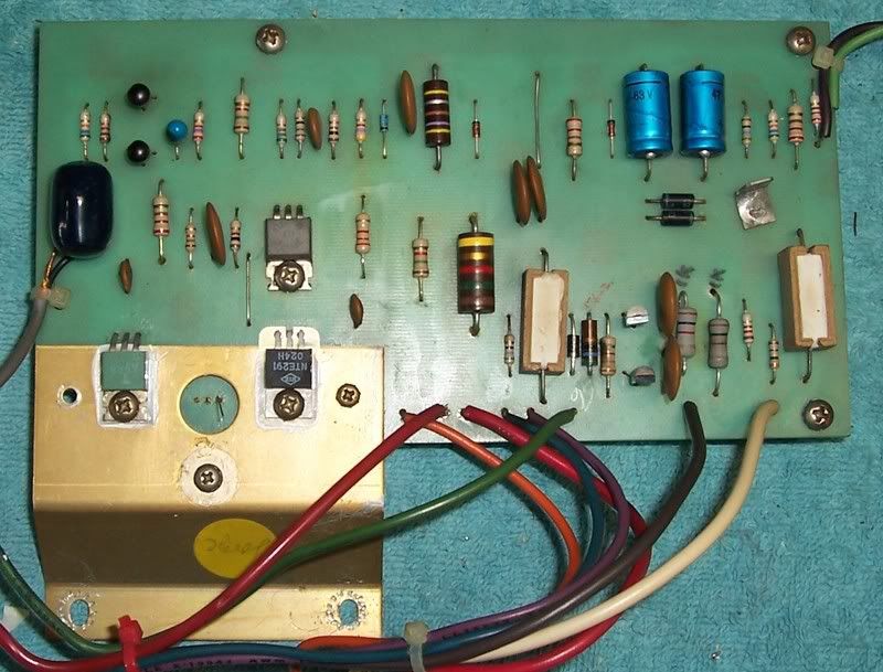
As you can see, it has all new transistors. I balanced the differential pair, biased the class A stage to dissipate 2W total, balanced the VI limiter and sundry other changes. The bias circuit was the biggest change. The plastic bias transistors are bonded to the heatsink and it tracks temperature better than diodes.
I haven't verified the VI limiter transistors for proper bias as of yet.
Gary
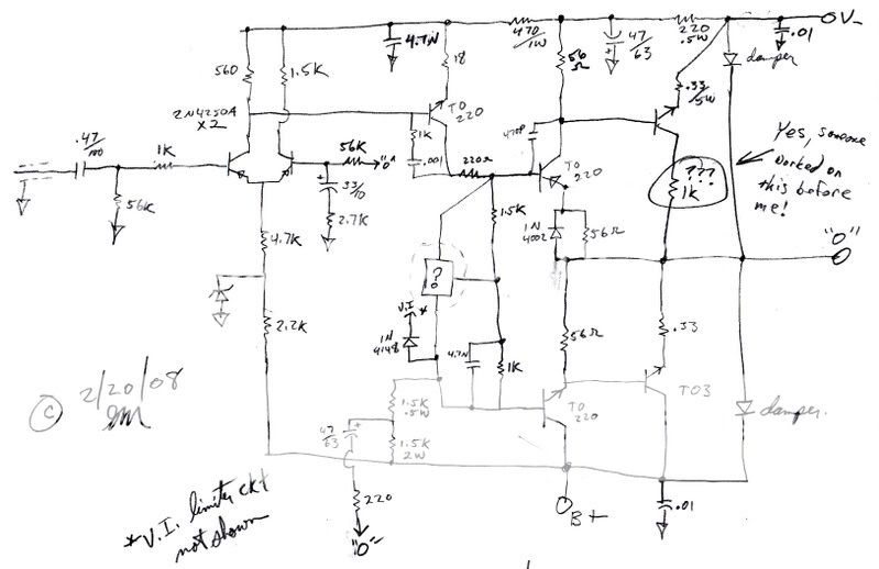
Here is my final schematic with mods for the Road Electronics amp. Got it fired up today and it sounds fine.
As you can see, it has all new transistors. I balanced the differential pair, biased the class A stage to dissipate 2W total, balanced the VI limiter and sundry other changes. The bias circuit was the biggest change. The plastic bias transistors are bonded to the heatsink and it tracks temperature better than diodes.
I haven't verified the VI limiter transistors for proper bias as of yet.
Gary

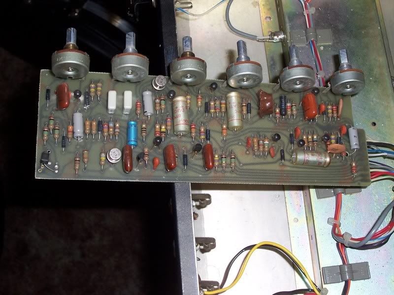
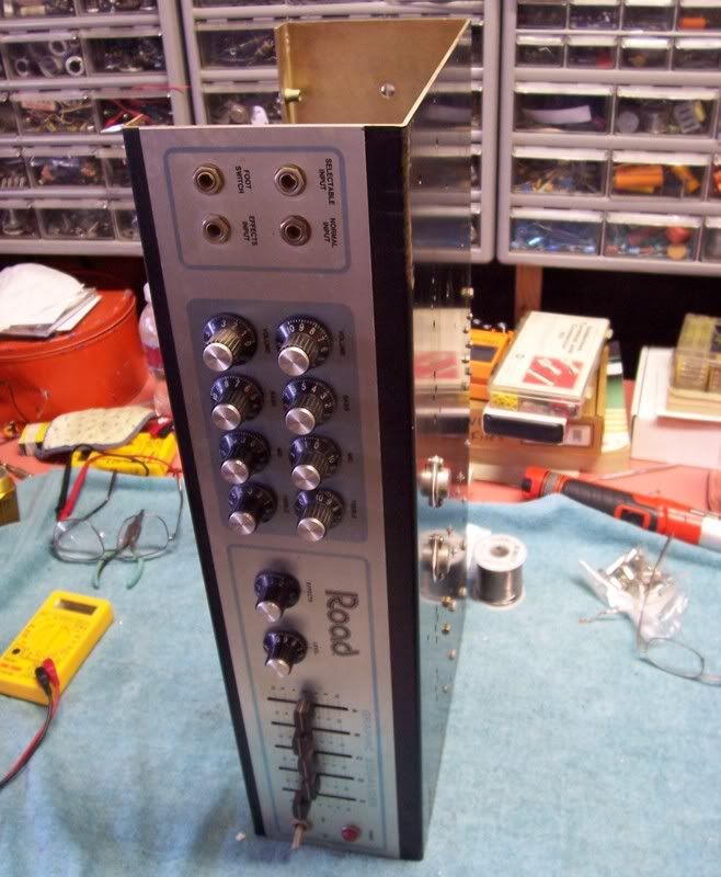

 I don't know if it's an NPN, PNP or what the pinout might be. As you can see, the device is literally blown. I've searched the Rickenbacker stuff and there was nothing for my amp. I was hoping someone might recognize it. It looks like this head...
